RUNNING GEAR OPERATION
32
Operating instructions • Load Carrier • 505410638-02 • 07/2019
!
WARNING
Improperly connecting and disconnect-
ing the supply and control connections
poses a risk of accident!
Improperly connected compressed air and
electrical lines affect driving and braking
behaviour and can lead to accidents.
► Observe the connection sequence of
the lines when hitching and unhitch-
ing.
► Always close the coupling heads with
the protective caps after unhitching
the brake lines.
For axle and brake control as well as air
and power supply, the trailer is equipped
with various connections on its front side.
The supply and control connections on the
coupling support of central axle trailers are
designed as a socket.
On turnframe trailers, the supply and con-
trol connections are fastened to the draw
fork as a strand with plugs.
1
2
3
4
5
6
Fig. 5-13:
Supply and control connections
on the central axle trailer
1
Vehicle lighting socket N ISO 1185, 7-
pin (black)
2
Vehicle lighting socket S ISO 3731, 7-
pin (white)
3
Supply compressed air coupling (red)
4
Brake compressed air coupling (yel-
low)
5
Vehicle lighting socket ISO 12098,
15‑pin
6
Brake EBS socket power supply ISO
7638
More information about the plug and
socket assignment can be found in the
technical data
(see "13.2 Plugs and socket pin
Coupling
Depending on the design, the following
couplings may be installed:
○
Standard coupling heads (standard),
○
Duo-Matic coupling and
○
C-coupling heads.
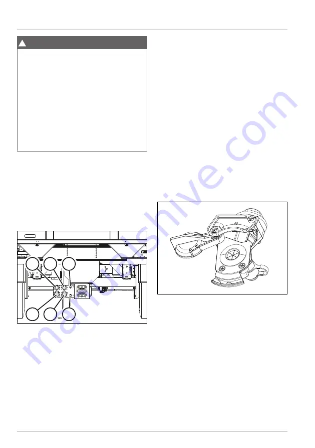
Connecting the standard coupling
Fig. 5-14:
Example of standard coupling
head
þ
The parking brake on the tractor unit is
applied.
þ
The parking brake on the trailer is ap-
plied
(see "5.9.2 Parking brake", pg. 37)
► Check the cleanliness and integrity of
the sealing surfaces on the coupling
heads. Clean if necessary.
► Always connect the brake compressed
air coupling (yellow) first.
► Connect the supply compressed air
coupling (red).


