Start-up
25
Pos : 12.29 /BA/Inbetri ebnahme/Vors ätz e/X-Disc 6200/Ankuppeln/Ankuppeln Bild T2 X-Disc 6200 @ 12\mod_1224679564016_78.doc @ 152872
GPS00017
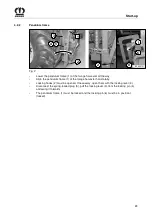
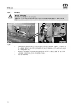
Fig. 9:
Pos : 12.30 /BA/Inbetri ebnahme/Vors ätz e/X-Disc 6200/Ankuppeln/Ankuppeln T 2 Verriegelungsgebel @ 12\mod_1224679658641_78.doc @ 152893
Swing the locking lever (3) to the rear and engage it on the locking pin (4), secure with spring
cotter pin (2).
Pos : 12.31 /BA/Inbetri ebnahme/Vors ätz e/X-Disc 6200/Ankuppeln/Hinweis korrektes Ei nhaken pr üfen @ 12\mod_1224679725172_78.doc @ 152914
Note
Check that the pendulum frame hooks correctly into the holding bolts (1) and the locking hooks
on both sides.
Pos : 12.32 /BA/Inbetri ebnahme/Vors ätz e/X-Disc 6200/Ankuppeln/Gelenkgabel aufschi eben @ 12\mod_1224679877235_78.doc @ 152935
•
Push the joint fork (5) onto the drive journal (6) of the main angular gearbox until the lock
engages.
•
Close the protective cover (7)
Pos : 12.33 /BA/Inbetri ebnahme/Vors ätz e/X-Disc 6200/Ankuppeln/Ankuppeln Bild T3 X-Disc 6200 @ 12\mod_1224680297641_78.doc @ 152978
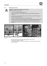
Fig. 10:
Pos : 12.34 /BA/Inbetri ebnahme/Vors ätz e/X-Disc 6200/Ankuppeln/Ankuppeln T 3 Text @ 12\mod_1224680422688_78.doc @ 152999
•
Unlock the pendulum frame and move the locking pin (1) from position I (locked) to
position II (unlocked).
•
Remove the bolts (3) from both sides of the parking supports (2).
•
Move parking supports (2) upwards and secure them in place with bolts (3) in the lowest
bore hole (4).
Pos : 12.35 /BA/-----Seitenumbruc h------ @ 0\mod_1196175311226_0.doc @ 4165


