background image

Introduction


Pos : 8.12.1 /Übersc hriften/Übersc hriften 2/A-E/Besti mmungsgemäß er Gebrauch @ 0\mod_1196401545090_78.doc @ 7728 


2.5 

Intended Use  

Pos : 8.12.2 /BA/Einl eitung/Bes ti mmungsgemäßer Gebrauc h/Vors ätz e/Besti mmungsgemäßer Gebr auc h X-Disc @ 12\mod_1224575491250_78.doc  @ 151478 


The direct cutting system may be attached only to carrier vehicles for which the relevant adapter 
frame is released (observe operating permission of the carrier vehicle). It is built exclusively for 
customary use in agricultural work (intended use) - see also Introduction chapter entitled 
"Purpose of Use". 

Pos : 8.12.3 /BA/Einl eitung/Bes ti mmungsgemäßer Gebrauc h/Nic ht besti mmungs g emäss  @ 0\mod_1196401324340_78.doc  @ 7690 


Any use of the machine for other purposes is deemed not to be in accordance with intended 
use. The manufacturer shall not be liable for any resulting damage; the user alone shall bear 
the risk. 

Operation in accordance with intended use also includes observing the operating, maintenance 
and service instructions specified by the manufacturer. 

Unauthorised modifications to the machine may affect the properties of the machine or disrupt 
proper operation. For this reason, unauthorised modifications shall exclude any liability of the 
manufacturer for consequential damage. 

Pos : 8.13 /BA/Einl eitung/T ec hnis che D aten @ 0\mod_1195566374865_78.doc @ 594 


2.6 

Technical data  

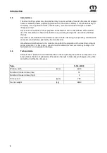
All information, illustrations and technical data in these operating instructions correspond to the 
latest state at the time of publication. We reserve the right to make design changes at any time 
and without notification of reasons. 


Pos : 8.14 /BA/Einl eitung/T ec hnis che D aten/Vorsätz e/X-Disc  6200 @ 12\mod_1224575736234_78.doc @ 151501 

wa 

Type   


X-Disc 6200 

Working width


[mm]  

6200 

Number of mower drums (low)


12 

Number of mower drums (high)


Drive speed 

[rpm]  

750 

Service weight  

[kg]


2650 


Pos : 9 /BA/-----Seitenumbr uc h------ @ 0\mod_1196175311226_0.doc  @ 4165 

Summary of Contents for X-Disc 6200

Page 1: ...ing system v T Typ1 v X Disc 6200 v v T Typ2 v v v T Typ3 v v v T Typ4 v v v T Typ5 v v v T Typ6 v v v T Typ7 v v v T Typ8 v v v T Typ9 v v v T Typ10 v v v T abMasch Nr v from serial no v 619 449 v T Bestell Nr v Order no v 150 000 056 00 en v B Titelbild v v 17 05 2010 ...

Page 2: ...r is authorised to compile the technical documents Spelle 17 05 2010 Dr Ing Josef Horstmann Managing Director Director of Design and Development Year of manufacture Machine No Pos 2 BA Vor wort Sehr geehrter Kunde 0 mod_1195626300326_78 doc 905 Dear customer Dear customer You have now received the operating instructions for the KRONE product which you have purchased These operating instructions co...

Page 3: ...3 5 PTO Operation 13 3 6 Maintenance 14 3 7 Unauthorised Conversion Modification and Spare Parts Production 15 3 8 Inadmissible Modes of Operation 15 3 9 Introduction 16 3 10 Position of the Adhesive Safety Stickers on the Machine 16 3 11 Position of the General Information Labels on the Machine 18 3 11 1 Re Ordering the Adhesive Safety and Information Labels 19 3 11 2 Affixing the Adhesive Safety...

Page 4: ... 44 8 10 1 Cutter Blades 44 8 10 2 Blade screw connection 45 8 10 3 Blade Quick Fit Device 46 8 10 4 Periodical Inspection of the Leaf Springs 47 8 10 5 Periodical Inspection of the Cutting Discs Blade Drums 48 8 10 6 Abrasion Limit 49 8 11 Blade Changing on Cutting Discs 50 8 11 1 Blade Screw Connection 51 8 11 2 Blade Quick Fit Device 52 8 12 Replacing the linings 53 8 13 Rotary hub with shear f...

Page 5: ...t Vorsätze Wei ter er Verlauf X Disc 12 mod_1224571947171_78 doc 151288 Note In the operating instructions which follow the direct cutting system will also be referred to as the machine Pos 6 4 BA Vor wort Beachten Sie für Maschi ne 0 mod_1195626904076_78 doc 944 Please note The operating instructions are part of your machine Only operate this machine after you have been trained to do so and accor...

Page 6: ... doc 151355 The direct cutting system of the X Disc 6200 series is a front attachment unit specially for the KRONE forage harvester BiG X It is used to cut crops growing on the ground except maize Pos 8 4 BA Ei nleitung Gültigkeit Vorsätze X Disc 6200 12 mod_1224573518140_78 doc 151378 2 2 Validity These operating instructions apply to the direct cutting system of the series X Disc 6200 Pos 8 5 Ü ...

Page 7: ...e identification plate represents a legal document and should not be altered or rendered illegible When asking questions concerning the machine or ordering spare parts be sure to provide type designation machine number and the year of manufacture of the relevant machine To ensure that these data are always available we recommend that you enter them in the fields above Note Authentic KRONE spare pa...

Page 8: ... damage the user alone shall bear the risk Operation in accordance with intended use also includes observing the operating maintenance and service instructions specified by the manufacturer Unauthorised modifications to the machine may affect the properties of the machine or disrupt proper operation For this reason unauthorised modifications shall exclude any liability of the manufacturer for cons...

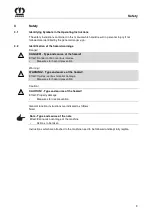
Page 9: ...on of the hazard warnings Danger DANGER Type and source of the hazard Effect Danger to life or serious injuries Measures for hazard prevention Warning WARNING Type and source of the hazard Effect Injuries serious material damage Measures for hazard prevention Caution CAUTION Type and source of the hazard Effect Property damage Measures for risk prevention Pos 10 4 BA Sicher heit Allgemeine Funktio...

Page 10: ... the safety instructions are not respected this could result in the forfeiture of any claims for damages Failure to follow the safety instructions could result for example in the following hazards Endangering of persons due to not protected working areas Breakdown of important machine functions Failure of prescribed methods for repair and maintenance Endangering of persons due to mechanical and ch...

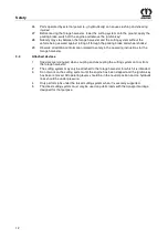
Page 11: ... coupling and uncoupling the cutting system onto or from the forage harvester 12 Always attach ballast weights properly to the fixing points provided 13 Observe permitted axle loads gross weight and transport dimensions 14 Check and install transport equipment such as lighting warning devices and protective equipment 15 Actuating mechanisms ropes chains linkage etc for remotely operated devices mu...

Page 12: ...ebaute Ger äte Ger äte angebaut X Disc 6200 12 mod_1224577829718_78 doc 151569 3 4 Attached devices 1 Special care is required when coupling and uncoupling the cutting system onto or from the forage harvester 2 The cutting system may only be attached to the forage harvester for which it is intended 3 Do not work on the cutting system until the engine has been stopped and the ignition key has been ...

Page 13: ...the permissible speed of the implement 9 Before switching on the PTO shaft make sure that no person is in the danger zone of the device 10 Never switch on the PTO if the engine is switched off 11 No one should be in the vicinity of the rotating PTO or PTO shaft when the PTO is in use 12 Always switch off the PTO shaft when the angle is too large or the PTO shaft is not required 13 Caution After di...

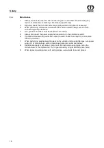
Page 14: ...ower supply before working on the electrical system 6 If protective devices and guards are subject to wear check them regularly and replace them in good time 7 When performing electrical welding work on the vehicle and mounted devices turn power supply off at main battery switch or disconnect generator cable and battery 8 Replacement parts must at least comply with the technical requirements set b...

Page 15: ...he manufacturer help to ensure safety Use of other parts may void liability for resulting damage Pos 10 6 15 BA Sicherheit U nzulässig e Betri ebsweisen 11 mod_1223357699923_78 doc 145527 3 8 Inadmissible Modes of Operation The operating safety of the delivered machine is guaranteed only when it is used as intended in compliance with the introductory section Intended use of the operating instructi...

Page 16: ...od_1195567214115_78 doc 674 Danger Danger zone of the machine Effect Danger to life or serious injuries Immediately replace damaged or illegible adhesive labels Following repair work always attach appropriate adhesive safety stickers to all the replaced modified or repaired components Never clean areas carrying an adhesive safety label using a high pressure cleaner Familiarise yourself with the st...

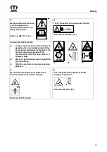
Page 17: ... time before being switched off completely Do not touch any moving parts of the machine Wait until they have come to a complete stop b Move the protective devices into position prior to start up c When the machine is running keep your distance 3a 3b 3c 4 Do not enter the danger zone between the front attachment unit and the machine Order No 942 312 0 2x 6 Close the protective equipment before putt...

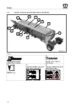
Page 18: ... Machine Pos 10 14 BA Sicherheit Aufkleber Vorsätze Hinweisaufkleber X Disc 12 mod_1224580031890_78 doc 151755 GPS00006_1 5 6 1 1 2 3 4 7 7 8 7 7 Fig 3 1 942 576 0 2x green 2 942 575 0 1x beige 3 942 393 0 1x length of 1400 beige 4 Farbe beige 942 577 0 1x 5 Order No 255 498 1 1x with blade screw connection 255 498 1 min 14 mm Ø 17 5 mm 80 5 Order No 255 499 2 1x with quick blade release 255 499 2...

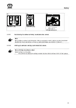
Page 19: ...lung Anbring ung Aufkleber 0 mod_1195637337107_78 doc 1079 3 11 1 Re Ordering the Adhesive Safety and Information Labels Note Every adhesive safety and information label is assigned an order number and can be ordered directly from the manufacturer or from an authorized dealer see Section Contact 3 11 2 Affixing the Adhesive Safety and Information Labels Note Affixing an adhesive label Effect Adhes...

Page 20: ...safety distance from the cutting tools during operation The glide skids must rest on the ground before start up and during work Stones and other objects may be hurled up even when the machine is used as intended For this reason no one is permitted in the danger zone Special care should be taken when working near roads and buildings Check the guard cloths regularly Worn or damaged guard cloths must...

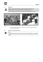
Page 21: ... GPS00008 2x Fig 4 Pos 12 7 BA Inbetriebnahme Vorsätze Anschlag punkte 12 mod_1224668047156_78 doc 152398 For transporting from one place to another onsite e g loading brace the lifting tool against the illustrated points Pos 12 8 Überschriften Überschriften 2 A E Anbau an den Feldhäcksler 13 mod_1225451434551_78 doc 156364 4 2 Attachment to the forage harvester Pos 12 9 BA Inbetriebnahme Vorsätze...

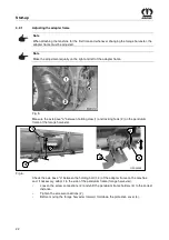
Page 22: ...669606297_78 doc 152571 Fig 5 Measure the axle base a between holding claw 1 and locking hook 2 on the pendulum frame of the forage harvester Pos 12 15 BA Inbetri ebnahme Vorsätze X Disc 6200 Adapterr ahmen Achsabstand Aufnahmebolzen prüfen Bild X Disc 6200 12 mod_1224676160969_78 doc 152613 1 2 a GPS00009 4 4 Fig 6 Pos 12 16 BA Inbetri ebnahme Vorsätze X Disc 6200 Adapterr ahmen Achsabstand Aufna...

Page 23: ..._78 doc 152722 Lower the pendulum frame 1 of the forage harvester all the way Align the pendulum frame 1 of the forage harvester horizontally Locking hooks 2 must be opened If necessary open them with the locking lever 3 Disconnect the spring loaded plug 5 pull the locking lever 3 from the locking pin 4 and swing it forwards Pos 12 22 BA Inbetri ebnahme Vorsätze X Disc 6200 Pendelrahmen Pendelrahm...

Page 24: ...peln Ankuppeln Bild T1 X Disc 6200 12 mod_1224679223094_78 doc 152830 1 2 3 4 5 GPS00010 1 Fig 8 Pos 12 27 BA Inbetri ebnahme Vorsätze X Disc 6200 Ankuppeln Ankuppeln T1 X Disc 6200 12 mod_1224679263125_78 doc 152851 Drive the forage harvester up to the machine until the pendulum frame is just in front of the adapter frame 1 and the holding bolts 3 are located against the stop surfaces of the hold...

Page 25: ...both sides Pos 12 32 BA Inbetri ebnahme Vorsätze X Disc 6200 Ankuppeln Gelenkgabel aufschi eben 12 mod_1224679877235_78 doc 152935 Push the joint fork 5 onto the drive journal 6 of the main angular gearbox until the lock engages Close the protective cover 7 Pos 12 33 BA Inbetri ebnahme Vorsätze X Disc 6200 Ankuppeln Ankuppeln Bild T3 X Disc 6200 12 mod_1224680297641_78 doc 152978 Fig 10 Pos 12 34 ...

Page 26: ...draulics and check that it is aligned horizontally If necessary compensate for any lateral inclination by changing the pretension on the tension spring 2 DANGER Unexpected actions on the machine Effect Danger to life injuries or damage to the machine Switch off the engine remove the ignition key and secure the machine from rolling away Change the pretension of the tension spring 2 by turning the h...

Page 27: ...injuries or damage to the machine The direct cutting system may only be used on public roads with the designated transportation trailer The transportation trailer is described in a separate set of operating instructions It is forbidden to carry passengers on the machine When driving on roads the general requirements or special conditions of the Road Traffic Type Approval Law StVZO and the Road Tra...

Page 28: ...r zone turn off the machine immediately Never leave the machine running unsupervised Check the safety devices each time before the machine is used Replace damaged safety devices immediately Do not work on the front attachment until the engine has been stopped and the ignition key has been removed All operating levers should be in the neutral position and no hydraulic lines should be under pressure...

Page 29: ...forage harvester info centre chapter entitled Lifting gear Pos 16 7 BA Bedi enung Vorsätze Schneidwer k Antri ebsdr ehzahl 750 beachten 12 mod_1224742253248_78 doc 153193 DANGER Observe drive speed Effect Danger to life or serious injuries Do not exceed the maximum drive speed of 750 rpm Pos 16 8 BA Bedi enung Vorsätze Schneidwer k Schneidwer k einsetzen 12 mod_1224742534795_78 doc 153282 Set max ...

Page 30: ...the forage harvester to prevent it from rolling back Use extreme caution when attaching implements to or detaching them from the forage harvester The accident prevention regulations must be complied with absolutely When detaching the machine do not walk between the forage harvester and the machine Pos 16 12 BA Bedienung Vorsätze Schnei dwer k Abbau T1 Bild X Disc 6200 12 mod_1224743185404_78 doc 1...

Page 31: ...44163748_78 doc 153389 Pull the joint fork 5 off the drive journal 6 of the main angular gearbox Open the locking hook 1 Disconnect the spring loaded plug 4 pull the locking lever 3 from the locking pin 2 and swing it forwards Lower the pendulum frame of the forage harvester until the receiving claws are below the holding bolts Move the forage harvester back Pos 17 BA Sei tenumbruch 0 mod_11961753...

Page 32: ...rly again Avoid skin contact with oils greases cleaning agents and solvents In the event of injuries or burns due to oils cleaning agents or solvents contact a doctor immediately All other safety instructions must also be followed to avoid injuries and accidents Pos 18 3 Überschriften Überschriften 2 A E Abstand Abstr eifleisten Förderschnecke einstellen 13 mod_1225692537051_78 doc 156478 7 1 Adju...

Page 33: ...with the raised machine always secure it with suitable supporting elements Close shut off valve on lifting cylinder of forage harvester After all repair maintenance and cleaning tasks are complete all protective covers and protective devices must be put in place again Pos 20 4 BA Sicher heit Gefahr enhinweise M ähwer ke Bei unr egel mäßiger Kontroll e der M esser klingen und Haltebolzen 0 mod_1196...

Page 34: ...mals nor objects are in the danger zone Start a trial run of the machine from the driver s seat only Pos 20 8 Überschriften Überschriften 2 A E Ersatzteil e 0 mod_1196782991234_78 doc 14927 8 2 Spare Parts Pos 20 9 BA Sicher heit Gefahr enhinweise M ähwer ke Ver wendung von nicht zug elassenen Ersatzteilen 0 mod_1196783037140_78 doc 14946 Danger Using non approved spare parts Effect Danger to life...

Page 35: ...ntenance 35 Pos 20 11 BA Diese Seite ist bewusst freigel assen wor den 1 mod_1201783680373_78 doc 54443 This page has been left blank deliberately Pos 20 12 BA Seitenumbruch 0 mod_1196175311226_0 doc 4165 ...

Page 36: ...0 M 24 730 1050 1220 M 24x1 5 350 M 24x2 800 1150 1350 M 27 1100 1550 1800 M 27x2 1150 1650 1950 M30 1450 2100 2450 A KR 1 130 Note The table above does not apply to countersunk screws with a hexagonal socket head if the countersunk screw is tightened with the hexagonal socket head Pos 20 14 BA Wartung Muttern und Schrauben 50h anzi ehen 0 mod_1196949864530_78 doc 15293 Note Regularly check that n...

Page 37: ...160 188 M 16 168 248 292 M 20 340 488 568 A BM 400 0234 Note The table above applies only to countersunk screws with hexagonal socket heads and metric threading that are tightened by the hexagonal socket head Pos 20 18 BA Wartung Muttern und Schrauben 50h anzi ehen 0 mod_1196949864530_78 doc 15293 Note Regularly check that nuts and bolts are tightly in place approx every 50 hours and tighten them ...

Page 38: ...orner gearbox 1 7 Cutter bar drive gear 1 1 Cutter bar 14 Pos 20 23 BA Wartung Zei tinter valle an den Getri eben 0 mod_1196951919921_78 doc 15373 8 5 1 Oil Level Check and Oil Change Intervals Gearboxes Note Oil level check and oil change gearboxes and lubricating the machine Effect Long expected service life of machine First oil change on all gearboxes after 50 operating hours then every 200 ope...

Page 39: ...ion screw 1 Oil level up to bore hole 1 If necessary top up the oil SAE 90 Screw the check screw 1 back in Pos 20 25 5 BA Wartung Öl kontrolle_Wechsel Öl wechsel Versi on1 Bel üftungsfilter 0 mod_1197010026283_78 doc 15747 Oil change For time intervals see Chapter Oil Level Check and Oil Change Intervals Gearboxes Screw out the screw plug 2 Collect the used oil in a suitable drip pan Screw in the ...

Page 40: ...vel up to bore hole 1 If necessary top up the oil SAE 90 Screw the check screw 1 back in Pos 20 27 5 BA Wartung Öl kontrolle_Wechsel Öl wechsel Versi on1 Bel üftungsfilter 0 mod_1197010026283_78 doc 15747 Oil change For time intervals see Chapter Oil Level Check and Oil Change Intervals Gearboxes Screw out the screw plug 2 Collect the used oil in a suitable drip pan Screw in the screw plug 2 Fill ...

Page 41: ...c oil level of the cutter bar drive gear on the inspection window 1 The oil level must be visible at least halfway up the inspection window 1 If required top up the oil 3 SAE 90 Pos 20 29 6 BA Wartung Öl kontrolle_Wechsel Öl wechsel Schauglas X Disc 6200 12 mod_1224837898010_78 doc 153785 Oil change For time intervals see Chapter entitled Oil Level Check and Oil Change Intervals Gearboxes Screw ou...

Page 42: ...ion key The cutting discs blade drums continue to run Do not leave the driver s cab until the cutting discs blade drums have come to a complete stop Pos 20 31 3 Ü berschriften Ü berschriften 3 K O M ähholm ausrichten 0 mod_1197017956815_78 doc 16042 8 9 1 Aligning the Cutter Bar Pos 20 31 4 BA Wartung Mähwerke M ähhol m ausrichten EasyC ut 3 mod_1204721803648_78 doc 72358 EC 0 001 Fig 19 Oil level...

Page 43: ...tting discs blade drums Effect Danger to life or serious injuries Switch off the engine and remove the ignition key The cutting discs blade drums continue to run Do not leave the driver s cab until the cutting discs blade drums have come to a complete stop Pos 20 31 9 BA Wartung Mähwerke Öl kontr olle Mähhol m Easycut 3 mod_1204723206930_78 doc 72428 Allow the machine to run briefly Do not leave t...

Page 44: ...c 16361 8 10 1 Cutter Blades Pos 20 33 4 BA Wartung Mähwerke Di e Bohrung der M ähklingen kann sich durch Verschleiß aufweiten 10 mod_1221048982715_78 doc 131675 The borehole on the cutter blades may spread due to wear Pos 20 33 5 BA Sicherheit Gefahrenhinweise Mähwerke Zu g eringe Materialstär ke an den M ähkli ngen_neu 3 mod_1204727167898_78 doc 72588 Danger Insufficient thickness of material on...

Page 45: ...olts Effect Danger to life or serious injuries At every blade changing check the thickness of the holding bolts material Damage or worn retaining bolts must always be replaced by sets on each cutting disc blade drum The material thickness of the retaining bolts must not be less than 14 mm at the weakest point EC 240 0 min 14 mm Fig 22 Pos 20 33 9 BA Seitenumbruch 0 mod_1196175311226_0 doc 4165 ...

Page 46: ...es At every blade changing check the thickness of the holding bolts material Damage or worn retaining bolts must always be replaced by sets on each cutting disc blade drum The material thickness of the retaining bolts must not be less than 14 mm at the weakest point The material thickness of the leaf spring must not be less than 3 mm at the weakest point EC 239 0 min 14 mm Fig 23 Pos 20 33 11 BA S...

Page 47: ...n the leaf springs Effect Danger to life or serious injuries Check the leaf springs for damages at least once a day or after contact with foreign objects The abrasion limit of the leaf springs will be achieved if the application seam 1 is worn on one point EC 225 0 1 1 Fig 24 Note Use only original Krone spare parts to replace the leaf springs Pos 20 33 13 BA Seitenumbr uch 0 mod_1196175311226_0 d...

Page 48: ...Discs Blade Drums Effect Danger to life or serious injuries Check the cutting discs or blade drums for damages at least once per day or after contact with foreign objects In case of deformed cuttings discs or drums the dimension of A 48 mm must never be exceeded EC 0 211 A 1 Fig 25 Note The cutting discs or drums must be replaced by Original Krone spare parts only Pos 20 33 15 BA Seitenumbr uch 0 ...

Page 49: ...rums Effect Danger to life or serious injuries The abrasion limit 2 will be achieved if the min material thickness of 3 mm is no longer given EC 226 0 2 2 Fig 26 Note If cutting discs or blade drums show deformations or wear in form of abrasions 2 or similar these components have to be replaced by Original Krone spare parts Pos 20 33 17 BA Seitenumbr uch 0 mod_1196175311226_0 doc 4165 ...

Page 50: ...de drums continue to run Do not leave the driver s cab until the cutting discs blade drums have come to a complete stop Pos 20 33 20 BA Sicher hei t Gefahrenhi nweise M ähwer ke Sich lösende M ähkli ngen 0 mod_1197269483265_78 doc 16540 Danger Cutter blades coming loose Effect Danger to life or serious injuries After changing the blades check that they fit perfectly and that they can move freely W...

Page 51: ...lt from above and tighten it firmly for tightening torque see chapter entitled Torques Repeat this process for all blades even on the blade drums After fitting the blades fold the protective device down again Note The cutter blades of anticlockwise rotating cutting discs blade drums are different than those of clockwise rotating ones Make certain the direction of rotation is correct when installin...

Page 52: ...to the retaining bolt and allow the blade key to return upwards After fitting the blades fold the protective device down again Note The cutter blades of anticlockwise rotating cutting discs blade drums are different than those of clockwise rotating ones Make certain the direction of rotation is correct when installing The arrow on the cutter blades must match the direction of rotation of the corre...

Page 53: ...rial to the cutter bar material and to the lining or carry out a trial welding if necessary EC 0 012 Fig 29 Open the welding seams of the old lining Remove the lining Deburr the contact surface EC 252 0 Fig 30 Adapt the new lining 3 Weld short I seams on the upper surface of the cutter bar in the areas marked 1 each should be approx 30 mm Do not weld the edges 2 On the lower surface of the cutter ...

Page 54: ...mod_1213097920976_78 doc 86356 8 13 Rotary hub with shear fuse optional Pos 20 35 2 BA Wartung Mähwerke Schersicherung Bild Mähhol m Aufstellung X Disc 6200 12 mod_1224840255682_78 doc 153851 Fig 31 A Direction of rotation to the middle not provided Pos 20 35 3 BA Seitenumbruch 0 mod_1196175311226_0 doc 4165 ...

Page 55: ... Eccentric bearing housing anticlockwise threading with identifying groove Pos 20 35 6 BA Wartung Mähwerke Schersicherung Beschrei bung Schersicherung 3 mod_1204205493155_78 doc 69964 For protection against overload on the mowing units the rotary hubs 1 are secured with nuts 2 and shear pins 3 If the machine strikes obstacles for example stones the 2 shear pins in the rotary hub will be sheared of...

Page 56: ...the bearing housing not observed Effect Damage to the machine Right rotating RE RZ cutting discs and drums always have right handed pinion shafts and nuts no groove mark on the pinion shaft and nut Left rotating LE LZ cutting discs and drums always have left handed pinion shafts and nuts with groove mark on the pinion shaft and nut Pos 20 35 10 BA Wartung M ähwer ke Schersicher ung N ach dem Absch...

Page 57: ...e the new shear pins 3 through the hub 1 and shaft 4 Note Note the position of the shear pins Drive the shear pins 3 into the hole from outside until the end of the pin reaches the surface of the hub d he slots of the shear pins 3 must be mounted facing each other horizontally see detail I Install the nut 2 using the special key 10 included with delivery tighten to a tightening torque of 300 Nm In...

Page 58: ...nd remove the ignition key Secure the forage harvester against accidental start up and against rolling away Switch off the PTO and disengage it After the repair maintenance cleaning work or technical modifications are completed mount all protective covers and protective devices properly again Avoid skin contact with oils greases cleaning agents and solvents In the event of injuries or burns due to...

Page 59: ...e Schmi erstellen nach Betriebsstunden abschmier en 12 mod_1224841289385_78 doc 153941 The lubrication points mentioned below must be lubricated after the operating hours indicated Pos 20 37 9 BA Wartung Vorsätze Schmi erpl an X Disc 6200 12 mod_1224840967463_78 doc 153917 GPS00011 250h 250h 250h 25h 25h 25h 25h 25 h Fig 34 Pos 21 BA Sei tenumbruch 0 mod_1196175311226_0 doc 4165 ...

Page 60: ...llers etc to make certain they move easily If necessary remove clean grease and remount If necessary replace with new parts Use only original KRONE replacement parts Disassemble the PTO shaft Lubricate the inner tubes and the guard tube with grease Grease the lubrication points on the cross joint and on the bearing rings of the guard tubes Touch up damaged paint and preserve all uncoated areas tho...

Page 61: ...are completed mount all protective covers and protective devices properly again Avoid skin contact with oils greases cleaning agents and solvents In the event of injuries or burns due to oils cleaning agents or solvents contact a doctor immediately All other safety instructions must also be followed to avoid injuries and accidents Pos 22 7 BA Sicher heit Vorsätze Reparatur War tungs und R einigung...

Page 62: ... you are absolutely sure that neither persons animals nor objects are in the danger zone Start a trial run of the machine from the driver s seat only Pos 22 11 BA Ei nlag erung EasyC ut Vor der Saisaon ohne Bereifung 3 mod_1204731533226_78 doc 72767 Lubricate the machine thoroughly Remove any condensation water which may have collected in the bearings Check oil level in the gearbox es and top up i...

Page 63: ...nformation Required for Questions and Orders 7 Intended Use 8 Introduction 6 L Lubrication Chart 59 M Maintenance 14 33 Maintenance lubrication chart 58 O Oil Level Check and Oil Change Intervals Gearboxes 38 Oil level check and oil change on the cutter bar 42 Operation 28 P Periodical Inspection of the Cutting Discs Blade Drums 48 Periodical Inspection of the Leaf Springs 47 Personnel Qualificati...

Page 64: ...64 U Unauthorised Conversion Modification and Spare Parts Production 15 W Working position 28 ...

Page 65: ......

Page 66: ...abrik Bernard Krone GmbH Heinrich Krone Straße 10 D 48480 Spelle Postfach 11 63 D 48478 Spelle Phone 49 0 59 77 935 0 Fax 49 0 59 77 935 339 Internet http www krone de eMail info ldm krone de konsequent kompetent ...

Reviews: