7
EN
located on the opposite side of the lever must be tightened (half a rotation), lock again and check. Repeat the procedure until a positive effect is reached, namely, the lever cannot be
rotated while in locked position.
7. Tighten pedals to the crank with moments defined in this manual, remembering, that they have right-handed and left-handed threads, respectively (marked on the axis of the pedals).
8. If the model of the installed bicycle is a complete version, namely, equipped with mudshields and a light, one must remember that the wheel must be screwed in before it is installed.
In order to do this, first remove the mudshield from the wheel and install together with the lamp using a screw, placing them in the hole in the fork.
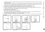
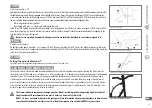
9. If the installed bicycle is a version without the mudshields and the light, a white reflective light is installed instead of the lamp, Fig. 6.
10. If the bicycle has a shock-absorbing fork, then the mudshield and the front light are installed on a handle which is located in the front part of the fork.
11. If the bicycle has horns of the handlebars attached, they must be installed at the ends of the handlebars, parallel to each other. Suggested inclination of the horns is ca. 45 degrees.
After adjustment, the horns of the handlebars must be tightened using moments defined in this instruction, Fig. 7.
In case of a bicycle with TDS type handlebars (Ahead):
1. Take the bicycle and attached elements out of the box.
2. Unclip the handlebars from the frame by removing tightening clipping bands.
3. Unscrew the front part of the handlebars support using a 6 mm or 5 mm Allen key and set the handlebars in thus created space, exactly in the middle of its length, parallel to the
ground. Then tighten the front part of the support using a 4 mm or 5 mm Allen key with moments defined in this instruction.
4. The following installation operations are repeated as in the case of a bicycle with a MTS support.
If this instruction does not include instructions on installation or removal of any part of the bicycle, please contact our support team, relevant information may also be found on websites of
the manufacturers.
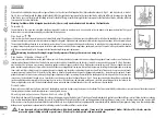
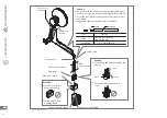
Fig. 1. Handlebars setting
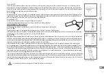
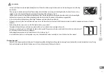
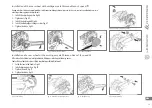
Fig. 2. Unclipping brake clutches
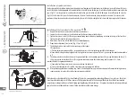
Fig. 3. Wheel installation
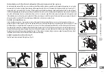
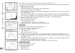
Fig. 4. Clipping brake clutches
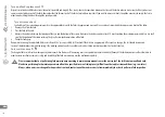
Fig. 5. Installation of seat support
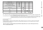
Fig. 6. Reflecting light installation
Fig. 7. Installation of handlebars horns


