background image

5 - INFORMACIONES TÉCNICAS

8

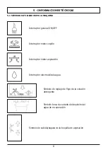
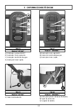
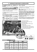
5.1 SIMBOLOS UTILIZADOS EN LA MAQUINA

Interruptor general ON/OFF

Interruptor motor cepillo

Interruptor motor aspiración

Interruptor electroválvula agua

Simbolo de reglaje de flujo de la solución
detergente

Simbolo boca de vaciado del depósito del
agua de recuperación

Simbolo de subida/bajada de la boquilla de aspiración

Summary of Contents for KF36BBC

Page 1: ...DORA DE PAVIMENTOS FLOOR SCRUBBER DRIER KF36E KF36BBC Technical data plate Placa dato técnicos ADVERTENCIA leer atentamente las advertencias antes el uso de aparado WARNING read the instructions carefully before use ...

Page 2: ......

Page 3: ...2 ESPAÑOL PAG 3 E ENGLISH PAG 26 GB ...

Page 4: ... 8 REGLAJE DE LA BOQUILLA DE SECADO 7 9 LLENADO Y DESCARGA DEL DEPÓSITO DE LA SOLUCIÓN LIMPIADORA 7 10 VACIADO DEL DEPÓSITO DE RECUPERACIÓN 7 11 REGULACIÓN DE LA CANTIDAD DE LA SOLUCIÓN DETERGENTE 7 12 CONDUCCIÓN DE LA MÁQUINA 7 1 MÉTODO DE TRABAJO 7 13 1 PREPARACIÓN Y ADVERTENCIAS 7 13 2 CONTROL DEL ESTADO DE CARGA DE LA BATERÍA 7 13 3 LAVADO DIRECTO O PARA SUPERFICIES LIGERAMENTE SUCIAS 7 13 4 L...

Page 5: ... vi tales para evitar graves o extremas consecuen cias a la salud de las personas y a la integridad del producto y del ambiente en el que se trabaja 2 3 IDENTIFICACIÓN DEL PRODUCTO La placa de datos situada debajo del panel de man dos contiene las siguientes informaciones identificación del fabricante marca CE código del modelo modelo potencia nominal total número de serie año de fabricación peso ...

Page 6: ...jemplo gaso lina aceite combustible etc no aspire nunca objetos en llamas o incandescentes No utilice la máquina en pendencias o rampas superiores al 2 Para transportar la máquina en rampas o en pen dencias más elevadas presta la máxima atención para evitar vuelcos y o aceleraciones incontroladas Desplace la máquina por rampas y o escalones sólo con el cabezal de los cepillos y la boquilla de se c...

Page 7: ...atería y el conector estén en buenas condiciones y que sean seguros para el operario Si no están en perfectas condiciones no utilice la má quina por ningún motivo antes de que un técnico especializado y autorizado realice la reparación Apague inmediatamente el motor de aspira ción si observa pérdidas de espuma o de líquido No utilice la máquina sobre superficies texti les como alfombras moquetas e...

Page 8: ...ar los riesgos de acci dentes La máquina está embalada en caja de cartón pue sta sobre un pallet de madera para el desemba laje de la máquina proceda del siguiente modo y por este orden Corte y quite los flejes de plástico con tijeras o ci zalla Quite sacándola por arriba la caja de cartón Saque las bolsas que están dentro de la caja y compruebe su contenido manual de uso y mante nimiento conector...

Page 9: ...tor general ON OFF Interruptor motor cepillo Interruptor motor aspiración Interruptor electroválvula agua Simbolo de reglaje de flujo de la solución detergente Simbolo boca de vaciado del depósito del agua de recuperación Simbolo de subida bajada de la boquilla de aspiración ...

Page 10: ...n C Tapa del alojamiento de l aspiración D Depósito de la solución detergente Foto 1 Foto 2 B A C A B A Pedal de desbloqueo del mango B Tubo de aspiración A Filtro de aspiración B Flotador C Tapon de inspección del depósito del agua de recuperación Foto 4 Foto 3 5 INFORMACIONES TÉCNICAS 5 2 ESTRUCTURA Y FUNCIONES DE LA MÁQUINA A ...

Page 11: ...e llave cortabatería B Tapón de protección C Cargador de batería Modelo KF36BBC Modelo KF36BBC B A C D A Interruptor general ON OFF B Interruptor motor aspiración C Interruptor electroválvula agua D Interruptor motor cepillo Modelo KF36E Foto 7 Foto 5 Modelo KF36E A Foto 8 Foto 6 A Cable de alimentación C 5 INFORMACIONES TÉCNICAS ...

Page 12: ...11 69 101 79 114 47 5 3 DIMENSIONES Todas las dimensiónes son indicadas en centímetros 104 81 5 INFORMACIONES TÉCNICAS ...

Page 13: ... desbloqueo levantar el mango hasta recoger la posición de blo queo en la posición de trabajo querida El mango tiene tres posiciones de bloqueo una po sición cerrada para el estacionamiento Foto 10 y dos posiciones de trabajo Foto 11 e Foto 12 Foto 9 Foto 10 Mango en posición cerrada Foto 11 Mango en posición intermedia Para limpiar en espacios muy limitados se aconseja trabajar con el mango en es...

Page 14: ...o los bornes exactamente y sólo en los polos marcados con el mismo símbolo cableado rojo cableado negro según el esquema de conexión de la batería en la foto 15 Un eventual cortocircuito de la batería puede ocasionar explosiones Una vez haya comprobado que todos los mandos en el panel estén en posición 0 o en reposo co necte el conector de la batería al conector posicio nado su el cuerpo de la máq...

Page 15: ...iguración DE LOS DIP SWITCH DEL CAR GADOR CBHD1 12V 6A Para hacer la configuración del cargador con tipo de carga para baterías PB Acido baterías GEL AGM o OPTIMA se necesita de obrar los interrupto res Dip Switch situados a l interior del car gador Foto 17 D Foto 17 F Para acceder a los dip switch se debe desmontar la tapa inferior del cargador Foto 17 A o el tapón en plástico Foto 17 E Para conf...

Page 16: ...ectangulares contiguas y paralelas entre sí Escoja una trayectoria de trabajo rectilínea y em piece a trabajar por la zona más lejana para evitar volver a pasar sobre las zonas que ya se han lim piado 7 2 RECARGA DE LA BATERÍA Conectar el cable de alargo al cable de alimenta ción del cargador Foto 19 A y conectar la ma quina a la red eléctrica Al encenderse el cargador de baterías efectúa una prue...

Page 17: ...de pro vocar daños a la máquina y al pavimento Compruebe regularmente el desgaste de estos componentes antes de empezar a trabajar Para el desmontaje o la sustitución Levantar la boquilla de secado por medio de la pa lanca de subida bajada Foto 2 B Empuñar el mango Foto 1 A y bajarlo ligera mente para levantar la parte delantera de la ma quina con una rotación sobre las ruedas traseras Seleccionar...

Page 18: ...e la boquilla de secado y desmon tar el listel de fijación del labio de goma Foto 24 B Sacar los tornillos de fijación Foto 24 C para desmontar el listel anterior de fijación Foto 25 A sacar los labios da el cuerpo de la boqui lla de secado Para la sustitución de los labios de goma montar los componentes en el orden contrario al desmon taje empezando da el labio delantero bloquear los tornillos de...

Page 19: ...on el suelo un ángulo de 45 Variando en modo apropriado la posición de las ruedas se puede arreglar la correcta presión de los labios La boquilla de secado debe secar de modo uni forme a lo largo de todo el frente de secado Tramos húmedos a los lados indican un secado in suficiente arreglar mediante las ruedas para opti mizar la eficacia Foto 25 B A A Listel delantero de fijación de el labio de go...

Page 20: ...pósito de la solución limpiadora Foto 29 A Tapón del filtro para el vaciado del depósito de la solución limpiadora cadas de la máquina Cerrar el depósito con el relativo tapón en esponja Para el vaciado Destornillar el tapón del filtro de la solución de tergente puesto en la zona inferior del déposito y esperar el completo vaciado Foto 29 A Atornillar firmemente el tapón del filtro 7 10 VACIADO DE...

Page 21: ...E Es posible reglar el flujo de salida de la solución de tergente a través del grifo situado sobre el grupo del cepillo Posicionar la palanca de regulación del flujo de la solución detergente en una posición intermedia entre el cierre Foto 31 y la abertura máxima Foto 33 según el tipo de lavado de efectuar La máquina es dotada con electroválvula y la salida de la solución detergente sólo ocurre en...

Page 22: ...gundo Recuerde que hay que levantar la boquilla de se cado antes de retroceder a fin de evitar averías a la boquilla de secado 7 13 MÉTODO DE TRABAJO 7 13 1 PREPARACIÓN Y ADVERTENCIAS Libere la superficie que se ha de tratar con instru mentos adecuados como aspiradores barredoras etc de todo residuo sólido libre Si no se realiza esta operación preliminar la suciedad sólida podría impedir el correc...

Page 23: ...el contacto con dichas partes puede causar graves lesiones y hasta la muerte Antes de efectuar cualquier operación en la má quina es preciso desconectarla de la red eléctrica No tocar nunca los cables eléctricos estropeados o que presenten signos de desgaste Antes de acceder a la instalación eléctricase debe apagar la máquina y desconectarla de la toma de corriente Si se notan cables eléctricos es...

Page 24: ...a de detergente y agua sobre el pavimento y aislar la porción de superficie para obtener la máxima depresión del motor de aspiración de este modo el secado de la máquina es perfecto Trabajando continuamente de este modo el canto vivo de la banda tiende a redonde arse o deteriorarse perjudicando el perfecto se cado para esto hay que sustituir los labios de la boquilla de secado Para cambiar los lab...

Page 25: ...or el fabricante de las baterías Recargue las baterías 8 9 2OPERACIONES SEMANALES Compruebar y si fuera necesario reemplazar el protectore contra salpicaduras Comprobar atentamente el perfil de los labios de la boquilla de secado y cámbielas si fuera necesario Compruebar que los tubos y los conductos de aspi ración no estén obturados Limpiar a fondo el depósito de la solución limpia dora y el de r...

Page 26: ...ica o está quemado Comprobar las conexiones y en el segundo caso hay que cambiar el motor 9 5 POCA ASPIRACIÓN La tapa del alojamiento del filtro de aspiración no está bien cerrada Cerrar fuertemente la tapa El tubo de aspiración el conducto de la boquilla de se cado o el vano de inspección están obstruidos Liberar y limpiar los conductos 9 6 EL MOTOR DEL CEPILLO O EL MOTOR DE ASPIRACIÓN NO SE PARA...

Page 27: ...E ADJUSTMENT 7 9 FILLING AND DRAINING THE SOLUTION TANK 7 10 DRAINING THE RECOVERY TANK 7 11 ADJUSTING THE SOLUTION WATER FLOW 7 12 DRIVING THE MACHINE 7 13 WORK METHOD 7 13 1 PREPARATION AND WARNINGS 7 13 2 BATTERY CHARGE LEVEL CONTROLS 7 13 3 DIRECT SCRUBBING OR FOR SLIGHTLY DIRTY SURFACES 7 13 4 INDIRECT SCRUBBING OR FOR VERY DIRTY SURFACES 7 13 5 POST SCRUBBING OPERATIONS 7 14 SPECIFIC INSTRUC...

Page 28: ...ous damage to the machine and to the environment in which it operates DANGER SYMBOL Vital information to avoid serious or extreme consequences affecting the health of persons and causing damage to the product and the environment in which it operates 2 3 PRODUCT IDENTIFICATION The nameplate located in the backside of the ma chine contains the following informations Manufacturer ID CE mark Model cod...

Page 29: ...ontrolled accelerations The machine can be handled on ramps and or steps only with the brush head and squeegee lifted off the ground Never park the machine on a slope Never leave the machine unattended with the key in and connected it may be left only after hav ing disconnected it and taken the key out and guar anteeing against accidental movements and if necessary disconnecting it from the electr...

Page 30: ...tely turn off the suction motor Do not use the machine on textile flooring such as rugs carpeting etc Wax foaming detergents or dispersions along the hoses may cause serious problems for the machine or clog the hoses 3 2 SCRAPPING OF THE MACHINE If the machine will no longer be used remove the batteries and dispose of them in accordance with the eco compatibility regulations as set forth in Eu rop...

Page 31: ...oods 4 3 UNPACKING Wear safety clothing and use adequate tools to limit the risks of accidents The machine is packed with in a cardboard housing placed on a wooden crate to unpack the machine carry out the following steps Use scissors or clippers to cut and eliminate the plastic straps Slip off the cardboard housing from the top of the packed machine Remove the envelops inside and check their con ...

Page 32: ...YMBOLS USED ON THE MACHINE General ON OFF switch Brush motor switch Suction motor switch Solenoid valve switch Symbol of the solution water flow adjustment Symbol of the recovery tank drain hole Symbol of the squeegee lifting lowering ...

Page 33: ...bar B Recovery water tank C Suction compartment cover D Solution water tank Photo 1 Photo 2 A Handlebar release pedal B Suction hose A Suction filter B Automatic shut off float C Recovery tank inspection plug Photo 4 Photo 3 5 2 MACHINE STRUCTURE AND FUNCTIONS 5 TECHNICAL INFORMATIONS ...

Page 34: ... ON OFF key battery cu tout switch B Protecting cap C Battery charger Model KF36BBC Model KF36BBC A General ON OFF switch B Suction motor switch C Solenoid valve switch for solution water outlet D Brush motor switch Model KF36E Photo 7 Photo 5 Model KF36E Photo 8 Photo 6 A Power supply cable 5 TECHNICAL INFORMATIONS A B C ...

Page 35: ...34 69 101 79 114 47 5 3 DIMENTIONS All dimentions are in centimetres 104 81 5 TECHNICAL INFORMATIONS ...

Page 36: ...ce it in the working position wished The handlebar can be set in three fixed positions one handlebar closed position for the machine storage or the machine transportation in a car Photo 10 and two handlebar opened working positions Photo 11 and Photo 12 Photo 9 Photo 10 Handlebar closed position Photo 11 Handlebar opened middle position To operate in small spaces it is recom mended to set the hand...

Page 37: ...ry connecting the terminals only on the poles marked with the same symbol red wiring black wiring as shown in the con nection diagram in Photo 15 A battery short circuit may cause an explo sion After checking that all the controls on the panel are in position 0 or at rest connect the battery con nector to the machine connector Photo 16 B Photo 16 shows the correct battery connection Close the batt...

Page 38: ... GREEN LED indicator Photo 17 C flashes 2 times the battery charger is set for GEL AGM or OPTIMA batteries The battery charger settings will be displayed even if the battery is not connected DIP SWITCH CONFIGURATION FOR CHARG ING CURVE SETTINGS FOR BATTERY CHARGER CBHD1 12V 6A To set the charging curve type for Pb Acid GEL AGM or OPTIMA batteries it is necessary to operate on the dip switches plac...

Page 39: ...nd begin work ing from the farthest area to avoid passing over areas that have already been cleaned 7 2 BATTERY CHARGING Connect the patch cord to the power cable of the battery charger Photo 19 A and to the mains power When switching on the battery charger CBHD1 will check the battery voltage and decide whether to start the charging process If the battery is not con nected to the battery charger ...

Page 40: ...vely worn brushes or exces sively thin abrasive disks may damage the machine and the floor Regularly check the wear on these parts before starting to work Disassembly or replacement Lift the squeegee using the lifting lowering lever Photo 2 B Holding the handlebar Photo 1 A push it dow nward in order to lift the front part of the machine by rotating it on the rear wheels Select the brush rotation ...

Page 41: ...mble the squeegee from its support see 7 5 Unscrew the knobs Photo 24 A and remove metal blade retainer Photo 24 B Extract the fixing bolts Photo 24 C and remove the front metal blade retainer Photo 25 A remove the squeegee rubber blades tearing them from a side To replace the squeegee rubber blades follow the same procedure on the contrary starting from the front blade lock the fixing bolts Photo...

Page 42: ...ves bends in all points forming an angle of 45 with the floor Changing properly the wheels position it is possible to adjust the squeegee pressure the squeegee dry ing must be uniform along the entire drying line damp patches mean that drying is insufficient ro tate the adjusting wheels to optimize drying Photo 25 B A A Metal retainer for front rubber blade B Front rubber blade Photo 26 Photo 27 B...

Page 43: ...lution tank filling opening Photo 29 A Water filter cap for the drainage of the solution tank To drain the tank Unscrew the cap of the water filter placed in lower part of the solution tank and wait untul the tank is completely empty Photo 29 A Screw the water filter cap firmly 7 10 DRAINING THE RECOVERY TANK The dirty water must be drained in accordance with national regulations The user is compl...

Page 44: ...is neces sary to operate the water valve placed over the brush unit Set the solution flow control lever in an interme diate position between the closed Photo 31 and fully opened Photo 33 position according to the kind of cleaning to be performed The machine is provided with a solenoid valve the solution water outlet occurs only when the machine is working by pulling the control lever Photo 2 A to ...

Page 45: ...INGS Remove any loose solid residue from the surface to be treated using suitable tools such as vacuum cleaners sweepers etc It this is not done the solid dirt might prevent the squeegee from operat ing correctly reducing drying efficiency Only trained personnel can drive this machine 7 13 2 BATTERY CHARGE LEVEL CONTROLS The sequence of lights of the battery charge control Photo 18 C B A shows the...

Page 46: ...ic cables that are defective or worn Before gaining access to the electrical system it is always necessary to disconnect the machine from the electrical source In the case of defective damaged or cracked electric cables replace immediately with authentic replacement parts The network of connections must be protected from water spray The patch cord for the connection of the machine to the mains pow...

Page 47: ...onstantly in this manner tends to round or to deteriorate the sharp edge of the strip thus reducing drying effi ciently This is why the squeegee strips must be re placed To replace the worn blades follow the instructions in the relative section Turn the blades around to wear down the other sharp corners or to install new ones 8 5 ACCESSORIES Remove and clean the brush or the abrasive pad disk To a...

Page 48: ...file of the squeegee blades and replace them if necessary Check that the suction hoses and conduits are not clogged Thoroughly clean the solution and recovery tanks For other models with the Pb Acid battery check the level of the electrolyte in all elements and if necessary top up with distilled water Refer to the battery manufacturer s detailed instructions Lift the filter compartment cover and c...

Page 49: ...is burned Check the connections and for the latter case replace the motor 9 5 INSUFFICIENT SUCTION The cover of the suction compartment is not per fectly closed Close it correctly The suction hose or the squeegee conduit are obstructed Clean out and remove any obstructions from the conduits 9 6 THE BRUSH MOTOR OR THE SUCTION MOTOR DOESN T STOP Stop the machine cutting off the main power supply and...

Page 50: ... conforme con las indicaciones del manual o por un uso imperfecto del aparato Conditions of Warranty All our appliances are subjected to rigorous tests and are covered by warranty against material or manufacturing defects for a period of 12 months The warranty comes into effect from the date of purchase The date of purchase is the date indicated on the receipt issued by the Reseller when the appli...

Page 51: ...use the designated gratis possibilities for return instead Español Como propietario de un aparato eléctrico o electrónico le está prohibido por ley a tenor de la Directiva de la UE 2002 96 CE del 27 de enero de 2003 sobre residuos de aparatos eléctricos y electrónicos y la legislación na cional de los estados miembros de la UE que haya incorporado esta directiva eliminar este producto o sus compon...

Page 52: ......

Page 53: ...EU y sus sucesivas modificaciones y también con la norma EN Declara bajo su propia responsabilidad que la màquina Declares under its responsability that the machine General manager Director general Pamplona 13 03 2017 Pol Agustinos C G Parcela B2 31013 PAMPLONA Navarra SPAIN Tfno 948 318 405 948 317 616 Fax 948 318 453 www kruger es Pol Agustinos C G Parcela B2 31013 PAMPLONA Navarra SPAIN Tfno 94...

Page 54: ...KRÜGER TECHNOLOGY S L B 82526583 Polígono Agustinos C G Parcela B2 31013 Pamplona Navarra ESPAÑA 34 948 343 393 info kruger es www kruger es ...

Reviews: