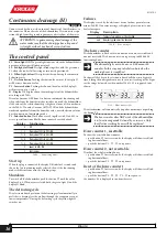
Continuous drainage (H)
KRG 240 HE
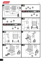
Connect a rubber hose, with an internal diameter of 14 millimeters, to
the connector H3 on the side of the dehumidifier. The connector is po-
sitioned high from the ground to guarantee a better flow of the water.
!
ATTENTION: to guarantee regular drainage of the
water, make sure that the drainpipe has a slope and
is straight, without any bends or constrictions.
The control panel
S1 - Green light ON
The green light indicates when the dehumidifier is
operative, otherwise it blinks on status 0.
S2 - Red light, full tank
The light blinks, together with the green one
S1, when the tank is full, missing or incorrectly positioned.
S3 - Yellow light, defrost
The light switches on during the automatic
defrosting cycle.
T1 - Decrease button
Pushing this button the value of the display D
will decrease down to 0 value.
T2 - Increase button
Pushing this button the value of the display D
will increase up to C value.
D - Display
The display shows the working state of the dehumidifier
according with Tab.A.
The value 0 means OFF, from 1 to 9 means automatic functioning and
it depends from the humidistat that switches on or off the dehumidifier
if the value of the relative humidity is higher or lower of the one shown
in the Tab.A. The value C means ALWAYS ON and the dehumidifier
works independently from the humidity value: nevertheless any alarm
has the priority on functioning mode.
T3 - Function button
This button is used together with S1 and S2 to
access special functions like the hour counter described ahead.
Display Functioning
0 Off
1 ÷ 2
from about 85% to 90% R.H.
3 ÷ 4
from about 70% to 80% U.R.
5 ÷ 6
from about 60% to 65% R.H.
7 ÷ 8
from about 45% to 55% R.H.
9
about to 40% R.H.
C Continuous
Tab.A – Functioning modes
Start up
When the plug is connected the display D blinks for 5 seconds and
shows the last functioning mode selected: then, if the functioning
mode is different from zero, the blinking stops.
Shutdown
To switch off the dehumidifier push the button T1 until the value
displayed is 0. When zero is selected both the green light S1 and the
display D blink.
The defrosting cycle
The electronic board performs the defrosting cycle automatically to
melt the ice keeping free the air flow through the evaporator even at
lower temperatures. During the defrosting cycle the yellow light S3
switches on.
Failures
The display is used by the electronic device to show particular situ-
ations (Tab.B). If an error message is displayed please contact your
dealer for repair.
Display Description
ntc
Temperature probe must be checked
und
Humidity probe must be checked
Tab.B – Error messages
The hour counter
The dehumidifier is fitted with two hour counters, one resettable and
one not resettable. The hour counter can register up to 999.999,99
functioning hours.
S
The decimal digits are in hours: so 0,50 means 30
minutes. In this way any calculation based on the
working hours is simplified.
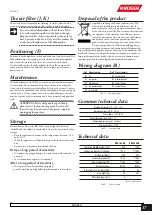
To show all the 8 digits the electronic board will show two digits at a
time, hiding the non significant ones: for a correct reading of the digits
see the image below where the number 554.433,22 is supposed to be
shown:
Pic.1 – Hour counter cycle
The visualization will automatically stop after one minute or pushing
the button T3.
S
The hour counter does NOT work if the dehumidifier
is in functioning mode 0, stand-by or in error. Only
the effective working hours will be registered.
Hour counter 1, resettable
To show the resettable hour counter:
• push button T3 for tree seconds: the display will show tree blink-
ing horizontal lines;
• push the buttons T1 - T1 - T3 in sequence.
Hour counter 2, not resettable
Tho show the whole working hours:
• push button T3 for tree seconds: the display will show tree blink-
ing horizontal lines;
• push the buttons T2 - T2 - T3 in sequence.
Reset of the hour counter 1
• push button T3 for tree seconds: the display will show tree blink-
ing horizontal lines;
• push the buttons T1 - T2 - T3 - T2 - T1 in sequence;
the number .00 is displayed to confirm the reset.
ENGLISH
16
M1070-2
Summary of Contents for KRG 160 HE
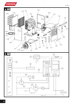
Page 2: ...B KRG 160 A KRG 160 2 M1070 2...
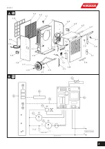
Page 3: ...B KRG 240 A KRG 240 3 M1070 2...
Page 4: ...C E E F H G D D KRG 240 KRG 160 KRG 160 KRG 160 KRG 160 KRG 240 4 M1070 2...
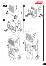
Page 5: ...K H J KRG 240 L 5 M1070 2...
Page 18: ...Notizen Note Notes 18 M1070 2...
Page 19: ...Notizen Note Notes 19 M1070 2...
Page 20: ......

