background image

ENGLISH

17

M1145-2_draft-0

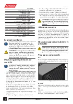
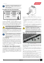
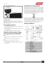
Operating principle

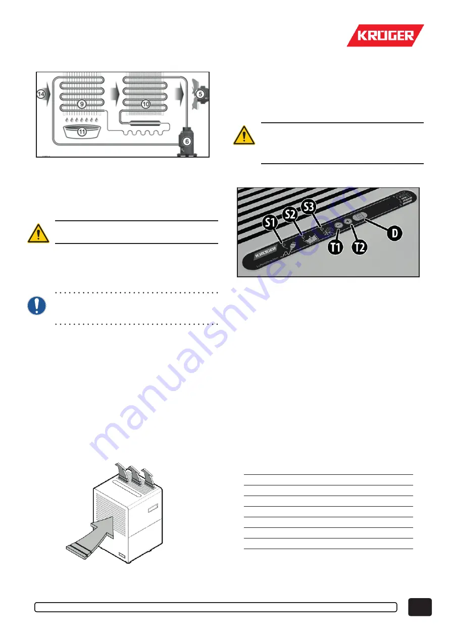
Pic.2 – 

Main components

The appliance uses a fan (5) to suck up the air (14) to be dehu-

midified and pass it through the refrigerator circuit evaporator 

(9). In this way the temperature of the air is lowered to below its 

dew point and the vapour condenses to form drops of water that 

are collected in the appropriate tank (11).

The water collected inside the tank is NOT drink-

able. Do NOT drink this water anyway.

The air thus dehumidified is passed through the condenser (10) 

that raises its temperature slightly higher than the initial value. 

In this way the quantity of humidity contained in the environ-

mental air is gradually decreased until it reaches the desired 

value.

When the dehumidifier works in a room it reduces 

the humidity of the walls and floor of the room, as 

well as in the materials contained therein.

The defrosting cycle

If the temperature goes below 16°C ice may form on the evapo-

rator (9). The ice must be regularly melted to prevent it from 

reducing the air passage. The electronic board automatically 

performs the defrosting cycle (see ahead). During the defrost-

ing cycle the compressor (6) stops. The time it takes to melt the 

ice changes with the humidity and temperature.

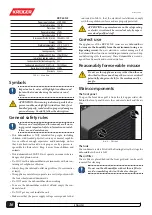
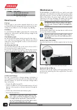
Installation and positioning

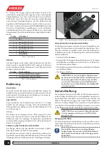
The KRP 60 NE series dehumidifiers must simply be placed in 

the room to be dehumidified and started. The dehumidifiers 

have the distinction of sucking the air from the front grid and 

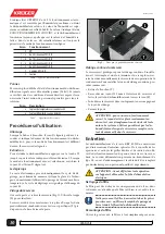
blowing it out from the top grid (Pic.3): this means that the de-

humidifier can even be placed between two pieces of furniture.

Pic.3 – 

Inlet and outlet of the air flow

To achieve maximum efficiency the following conditions must 

be met:

•  Make sure that in the room where the dehumidifier is in-

stalled the conditions never exceed the working limits of the 

machine (Tab.A);

•  The room where the dehumidifier is installed must be closed;
•  It is advisable to place the dehumidifier in the coldest point 

of the room, where normally the humidity level is higher, 

possibly near the power socket.

WARNING: This dehumidifier is NOT suitable for 

environments like laundry, or similar, where splash-

ing or dripping can penetrate water inside through 

the upper air grid.

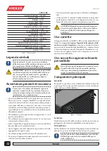
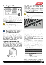
Control panel

Pic.4 – 

The control panel

S1 - Green light ON The green light indicates when the dehu-

midifier is operative, otherwise it blinks on status 0 (powered 

but off).

S2 - Red light, full tank The light blinks, together with the green 

one S1, when the tank is full, missing or incorrectly positioned.

S3 - Yellow light, defrost The light switches on during the auto-

matic defrosting cycle.

T1 - Decrease button Pushing this button will decrease the val-

ue of the display D down to 0.

T2 - Increase button Pushing this button will increase the value 

of the display D up to C.

D - Display The display shows the working state of the dehu-

midifier according to the table below (Tab.B). The value 0 means 

OFF, from 1 to 9 means automatic functioning and is controlled 

by the humidistat that switches the dehumidifier on or off if the 

value of the relative humidity is higher or lower than the one 

shown in Tab.B. The value C means ALWAYS ON and the dehu-

midifier works independently from the humidity value: never-

theless, any alarm has priority over the functioning mode.

  Display Functioning


0 Off


1 ÷ 2 

from about 85% to 90% R.H.


3 ÷ 4 

from about 70% to 80% U.R.


5 ÷ 6 

from about 60% to 65% R.H.


7 ÷ 8 

from about 45% to 55% R.H.


about to 40% R.H.


C Continuous

Tab.B – Functioning modes

Failures

The display is used by the electronic device to show particular 

situations (Tab.C). If an error message is displayed please con-

Summary of Contents for KRP 60 NE

Page 1: ...ES DE L ITALIEN TRANSLATION OF THE ORIGINAL INSTRUCTIONS ENGLISH Air dehumidifier instruction manual FRANÇAIS Déshumidificateur d air manuel d instructions DEUTSCH Luftentfeuchter Bedienungshandbuch ITALIANO Deumidificatore d aria manuale d istruzioni Luftentfeuchter KRP 60 NE ...

Page 2: ...2 M1145 2_draft 0 ...

Page 3: ...3 M1145 2_draft 0 ...

Page 4: ...enthalten kann Die Gitter für den Ein und Austritt der Luft müssen immer freigehalten werden mindestens 10cm Abstand einhalten Das Gerät muss in der Vertikalen auf den vier Rädern ste hend betrieben werden Während des Betriebs das Gerät nicht bewegen Um das Gerät zu verstellen muss es zunächst ausgeschaltet und der Kondenswasserbehälter geleert werden Keinen Fremdkörper in das Gerät einführen Über...

Page 5: ...er Baureihe KRP 60 NE werden einfach in den zu entfeuchtenden Raum gestellt und eingeschaltet Die Besonderheit dieser Luftentfeuchter besteht darin dass sie die Raumluft an der Vorderseite ansaugen und die entfeuchtete Luft nach oben abgeben Abb 3 weshalb das Gerät auch zwischen zwei Möbelstücke gestellt werden kann Abb 3 Lufteinlass und auslass Um den Wirkungsgrad des Gerätes maximal nutzen zu kö...

Page 6: ...rung des Kondenswasserbehälters Die Klappe öffnen und den Behälter herausziehen Abb 5 Über den Schieber L das Wasser ausgießen Der Behälter muss dann wieder in seinen Sitz geschoben wer den hierbei müssen die beiden Füßchen an der Unterseite in die Öffnungen S in der Auflage einrasten Die Klappe schließen Abb 5 Positionierbohrungen für den Kondenswasserbehälter Dauerablauf am Kondenswasserbehälter...

Page 7: ...eibung drehen Das Gerät den in dieser Anleitung enthaltenen Anweisungen entsprechend einschalten Entsorgung des Gerätes Das Symbol der durchgestrichenen Mülltonne weist darauf hin dass das Produkt am Ende seiner Nutzdauer getrennt von an deren Abfällen gesammelt werden muss Der Benutzer muss deshalb das Gerät am Ende seiner Nutzdauer einer Sammel stelle für Elektro und Elektronikaltgeräte zuführen...

Page 8: ... des sulfures ou du chlore Gardez les grilles d entrée et de sortie de l air toujours libres laissez au moins 10 centimètres d air Cet appareil doit fonctionner en position verticale posé sur les quatre roues Ne déplacez pas l appareil pendant son fonctionnement Pour déplacer l appareil il faut tout d abord l éteindre puis vi der le bac de récupération de la condensation N insérez pas d objets étr...

Page 9: ...nt simplement introduits dans le milieu à déshumidifier et mis en marche Ces déshumidificateurs ont la particularité qu ils aspirent l air par l avant et soufflent l air déshumidifié vers le haut Figure 6 cela permet de positionner le déshumidificateur même entre deux meubles Fig 3 Entrée et sortie de l air Pour obtenir un rendement maximal respecter les normes sui vantes Vérifiez que dans le mili...

Page 10: ... du réservoir Ouvrez la porte et retirez le réservoir Fig 5 Utilisez la trappe L pour vider l eau Le réservoir doit être ensuite remis à sa place afin que les deux pieds inférieurs s emboitent dans les trous spécifiques S pré disposés sur la base Fermez la porte Fig 5 Trous pour le positionnement du réservoir Vidange continu du réservoir Le réservoir est prédisposé pour la vidange continue L insta...

Page 11: ...ination du produit Le symbole de la poubelle sur roues barrée indique que le pro duit à la fin de sa vie opérationnelle doit être collecté séparé ment des autres déchets L utilisateur devra par conséquent re mettre l appareil arrivé en fin de vie opérationnelle aux centres de collecte sélective des déchets électriques et électroniques ou bien le remettre à votre revendeur lorsque vous achetez un n...

Page 12: ...aria lasciare almeno 10 centimetri d aria Questo apparecchio deve funzionare in posizione verticale appoggiato sulle quattro ruote Non muovere l apparecchio durante il funzionamento Per spostare l apparecchio prima spegnerlo e svuotare la va schetta di raccolta della condensa Non inserire alcun oggetto estraneo all interno dell apparec chio Assicurarsi che la tensione di alimentazione corrisponda ...

Page 13: ...ti nell ambiente da deumidificare e messi in funzione Questi deumidificatori hanno la peculiarità che aspirano l aria da davanti e soffiano l aria deumidificata verso l alto Fig 3 ciò permette il posizionamento del deumidificatore anche tra due mobili Fig 3 Ingresso e uscita dell aria Per ottenere il massimo rendimento rispettare le seguenti con dizioni Assicurarsi che nell ambiente in cui viene i...

Page 14: ...to del serbatoio Aprire lo sportello e sfilare il serbatoio Fig 5 Utilizzare lo sportellino L per svuotare l acqua Il serbatoio dev essere poi rimesso al suo posto in modo che i due piedini inferiori s infilino negli appositi fori S predisposti sulla base Chiudere lo sportello Fig 5 Fori per il posizionamento del serbatoio Scarico continuo del serbatoio Il serbatoio è predisposto per lo scarico co...

Page 15: ...to manuale Smaltimento del prodotto II simbolo del cassonetto barrato indica che il prodotto alla fine della propria vita utile deve essere raccolto separatamente dagli altri rifiuti L utente dovrà pertanto conferire l appa recchiatura giunta a fine vita agli idonei centri di raccolta diffe renziata dei rifiuti elettrici ed elettronici oppure riconsegnarla al rivenditore al momento dell acquisto d...

Page 16: ... inlet and outlet air grids free 10 centimetres at least The appliance must always operate in a vertical position with the four wheels turned downwards Do NOT move the dehumidifier when working To move the dehumidifier switch it off and empty the con densate tank Do NOT put any tool inside the unit Make sure that the power supply voltage corresponds to that indicated in Tab A that the electrical i...

Page 17: ...ure that in the room where the dehumidifier is in stalled the conditions never exceed the working limits of the machine Tab A The room where the dehumidifier is installed must be closed It is advisable to place the dehumidifier in the coldest point of the room where normally the humidity level is higher possibly near the power socket WARNING This dehumidifier is NOT suitable for environments like ...

Page 18: ... Connect a rubber hose with an internal diameter of 10 mil limetres to the connector on the tank and run it through the hole F Put the tank with the drain tube back in its place Then close the front door ATTENTION to guarantee regular drainage of the water make sure that the drainpipe has a slope and is straight without any bends or constrictions In any case the floating device inside the tank is ...

Page 19: ...other waste at the end of its useful life The user must therefore take the appliance at the end of its useful life to a special centre for electrical and electronic waste collection or hand it back to the retailer upon purchase of a new product of an equivalent type on a one for one basis Proper segregated waste collection of old appliances for subse quent recycling treatment and environmentally c...

Page 20: ......

Reviews: