KMPS-1-64 Manual
12/18
KM 8000 Rev. A
Page 8 of 40
Copyright © 2018 Kulite Semiconductor Products, Inc.
All Rights Reserved.
2.1
Internal Connections
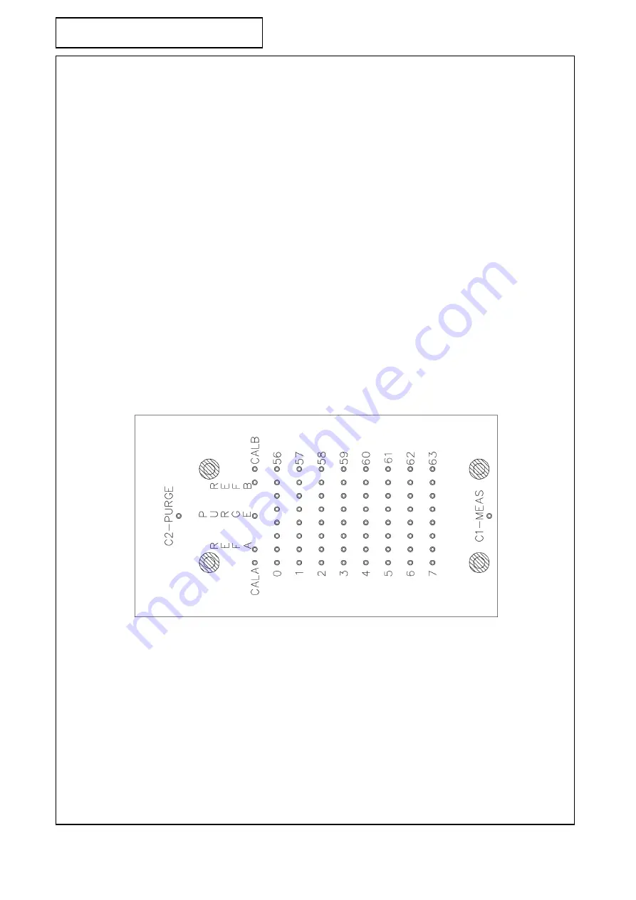
The KMPS-1-64 has an internal purge manifold which allows for the KMPS-1 to be placed
either in measure mode or purge/calibration mode by supplying pressure either to the MSR
input or PRG input on the two ends of the KMPS (see figure 2). Under normal conditions 100
PSI is required to move the manifold but at temperatures below -40°F pressures as high as
200 PSI may be required.
In measure mode the front of each of the 64 sensors is connected directly to one of the bulged
tubulations on the top of the KMPS. If the sensor is differential the back is connected to a
reference manifold which is connected to one of the two reference tubes (REFA or REFB)
depending on which side of the scanner the sensor is on.
When the manifold moves into purge/calibration mode the sensors become disconnected from
the top tubulations. Instead all of the tubulations are connected to the purge input allowing
for high pressure air to be blown out of the tubes clearing away moisture or obstructions. At
the same time the front of all of the sensors are connected together and connected to one of
the calibration tubes (CALA or CALB) allowing for an in place calibration of the scanner.
WHEN IN CAL MODE IT IS IMPORTANT NOT TO APPLY HIGHER PRESSURE THAN THE
LOWEST RANGE SENSOR CAN HANDLE.
The backs of the sensors remain connected to the reference manifold which is still connected
to the reference input. In this way it is possible to calibrate higher pressure absolute sensors
by raising the pressure of both the CAL and REF1 inputs simultaneously so that no differential
pressure is applied to low pressure differential sensors.
Figure 2: Drawing of top of KMPS-1
Summary of Contents for KMPS-1-64 Series
Page 1: ......


