7.4.3 Dismantling the pump section
Dismantle the pump section in accordance with the relevant general assembly
drawing. (
7.4.3.1 Removing the back pull-out unit
1. Unscrew screwed connection 902.01 and 920.01 and pull the complete back pull-
out unit out of pump casing 101.
2. Place the back pull-out unit in a safe and dry installation area and secure it
against tipping over or rolling off.
7.4.3.2 Removing the impeller
7.4.3.2.1 Removing the impeller with tapered fit
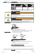
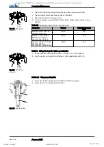
1. Unscrew socket head cap screw 914.10 with disc 550.23.
2. Completely screw the grub screw into the shaft thread.
3. Use a forcing screw to pull off impeller 230.
NOTE
The forcing screw is not included in the scope of supply. It can be ordered separately
from KSB.
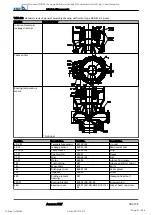
Table 21: Forcing screws for pulling off the impeller
Pump size
Impeller type
Forcing screw
Thread
Code
40-250
F, K, S
M16
ADS 1
80-250
E, F
100-240
F
100-250
E, F, K
80-251
F
M20
ADS 2
80-315
E, F, K
80-316
F
100-315
E, F, K
150-315
E, F, K
200-315
200-316
100-251
D
M16
ADS 3
150-251
80-315
D
M20
ADS 4
100-315
100-316
150-315
200-315
80-315
D - reinforced
bearing assembly
M24
ADS 5
100-315
150-400
D
M24
ADS 5
150-401
200-400
914.10
550.23
230
Fig. 21: Removing the
impeller
7 Servicing/Maintenance
44 of 74
Amarex KRT
Goodnal STP ST041 Sewage Delivery (Amarex KRT Submersible Motor Pump) Vendor Manual
Q-Pulse Id VM362
Active 29/10/2013
Page 46 of 96

