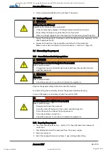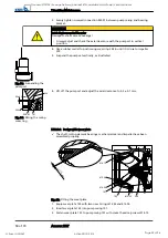
4. Adjust the clearance between impeller 230 and wear plate 135 by loosening and
tightening screws 914.12 and 914.24.
⇨
Screw 914.24 pushes the wear plate in the direction of the impeller.
⇨
The clearance equals 0.4
+0.2
mm (measured on the suction side from the
outer surface of the impeller vane to the wear plate).
5. Insert the complete back pull-out unit into the pump casing.
6. Evenly tighten screwed connection 920.01 between pump casing and bearing
bracket.
7.5.3 Reassambling the motor section
NOTE
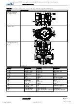
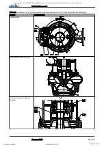
Before reassembling the motor section, check that all joints relevant to explosion
protection (flamepaths) are undamaged. Any components with damaged flamepaths
must be replaced. Only use original spare parts made by KSB for explosion-proof
pumps. Observe the flamepath positions specified in the Annex. Secure all screwed
connections closing off a flameproof enclosure with a thread-locking agent (Loctite type
243).
DANGER
Incorrect screws are being used
Explosion hazard!
▷
Always use the original screws for assembling an explosion-proof pump set.
▷
Never use screws of different dimensions or of a lower property class.
7.5.4 Performing a leak test
After reassembly the mechanical seal area/lubricant reservoir must be tested for
leakage. The lubricant filler opening is used for leak testing.
Observe the following values for leak testing:
▪
Test medium: compressed air
▪
Test pressure: 0.8 bar (max.)
▪
Test period: 2 minutes
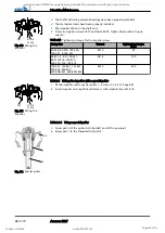
P
0.5 bar
Fig. 33: Screwing in the testing device
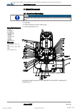
1. Unscrew and remove the screwed plug and joint ring of the lubricant reservoir.
2. Tightly screw the testing device into the filler opening for the lubricant.
3. Perform the leak test to the above conditions.
The pressure must not drop during the test period.
If the pressure does drop, check the seals and screwed connections.
Then perform another leak test.
7 Servicing/Maintenance
Amarex KRT
51 of 74
Goodnal STP ST041 Sewage Delivery (Amarex KRT Submersible Motor Pump) Vendor Manual
Q-Pulse Id VM362
Active 29/10/2013
Page 53 of 96

