background image

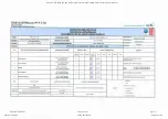
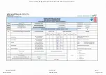
UNITS REV

DESCRIPTION

PURCHASER'S REQUIREMENTS

VENDOR OFFER

1.

2.

3.

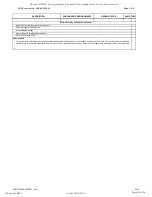
General Notes

The system duty, flowrate per pump and operation configuration nominated are for the purpose of sizing the pump units. Pump arrangement should allow 
standby pump to operate in parallel with duty pumps (ie in duty / duty assist arrangement) if required for instantaneous flows greater than the system duty 

General Arrangement Drawings

Sectionalised Drawings

Manufacturer's Pump Specification Sheet

Pump Performance Curve

Information to be submitted with Tender

Spare Parts for two (2) years & itemised cost

GDSTP

24090

DST

0011_A.xls

3


of


3

KSB Document No: KSB-88980-024

Page 3 of 9

Goodnal STP ST041 Sewage Delivery (Amarex KRT Submersible Motor Pump) Vendor Manual

Q-Pulse Id VM362

Active 29/10/2013

Page 87 of 96

Summary of Contents for 88980/20

Page 1: ...s PU 0200 010 020 OPERATING AND MAINTENANCE INSTRUCTIONS K S B A u s t r a l i a P t y L t d A B N 2 9 0 0 6 4 1 4 6 4 2 A Q u a l i t y E n d o r s e d C o m p a n y A S N Z I S O 9 0 0 1 2 0 0 8 Sal...

Page 2: ...Liquor 3 Drawings Certified G A Drawing No A3 UK00019 Site Foul Liquor Pumps Certified G A Drawing No A3 UK00018 PTA Foul Liquor Pumps 4 Tests I T P s Site Foul Liquor Pumps I T P s PTA Foul Liquor P...

Page 3: ...sizes 2 pole 5 2 to 55 2 4 pole 5 4 to 65 4 6 pole 4 6 to 50 6 8 pole 10 8 to 35 8 Installation Operating Manual Ident number 01196129 Goodnal STP ST041 Sewage Delivery Amarex KRT Submersible Motor P...

Page 4: ...uted copied reproduced processed for any other purpose nor otherwise transmitted to a third party without KSB s express written consent Subject to technical modification without prior notice KSB Aktie...

Page 5: ...horised modes of operation 11 2 10 Explosion protection 11 3 Transport Temporary Storage Disposal 13 3 1 Transport 13 3 2 Storage and preservation 13 3 3 Return to supplier 14 3 4 Disposal 14 4 Descri...

Page 6: ...bling the pump set 46 7 6 Tightening torques 52 7 7 Spare parts stock 52 8 Trouble shooting 54 9 Related Documents 55 9 1 General assembly drawings 55 9 2 Wiring diagrams 67 9 3 Flamepaths of explosio...

Page 7: ...tal and health hazards arising from components in contact with the fluid handled Close coupled design Motor directly fitted to the pump via a flange or a drive lantern Hydraulic system The part of the...

Page 8: ...K D K D K K K K K 200 316 K K K K K K 200 330 K K K K K K K 200 400 D D D 200 401 E K E K K K K K K 250 400 D K D K D K K K K K 250 401 K K K K K K K 300 400 D K D K D K K K K K 300 401 K K K K K K K...

Page 9: ...t Sub supplier documentation1 Operating manuals and other documentation of accessories and integrated machinery components Spare parts lists1 Description of spare parts Supplementary operating instruc...

Page 10: ...UTION this symbol indicates a hazard for the machine and its functions 2 2 General This manual contains general installation operating and maintenance instructions that must be observed to ensure safe...

Page 11: ...the system prevention of cavitation damage For any operating modes which are not specified in the data sheet or product literature contact the manufacturer Only use the respective impeller types in co...

Page 12: ...the personnel Training on the pump set must always be supervised by technical specialist personnel 2 5 Consequences and risks caused by non compliance with these operating instructions Non compliance...

Page 13: ...n commissioning Section 6 1 Page 32 2 9 Unauthorised modes of operation Never operate the pump set outside the limits stated in the data sheet and in this manual The warranty relating to the operating...

Page 14: ...nce with the manufacturer s instructions Repair to the values in tables 1 and 2 of EN 60079 1 is not permitted 2 Safety 12 of 74 Amarex KRT Goodnal STP ST041 Sewage Delivery Amarex KRT Submersible Mot...

Page 15: ...hat the following measures be taken for pump storage CAUTION Improper storage Damage to the power cables Support the power cables at the cable entry to prevent permanent deformation Only remove the pr...

Page 16: ...th oxygen the pump set must also be neutralised and anhydrous gas must be blown through the pump for drying purposes 4 Always complete and enclose a certificate of decontamination when returning the p...

Page 17: ...abrir bajo tensi n Do not open while energised 2 1 3 4 5 6 7 8 9 10 11 12 13 14 15 17 18 19 16 Amarex KRTK 150 315 164UG S Typ Amarex KRTK 150 315 164XG S No 9971143406 2007 Q 300 m3 h DKN 160 4 12 3...

Page 18: ...ic system Motor size and number of poles 372 552 554 504 654 D 80 315 X X D 100 315 X X D 150 400 X X X D 150 401 X X D 200 400 X X D 250 400 X X X Drive Three phase asynchronous squirrel cage motor E...

Page 19: ...e impeller the shaft 4 enters the casing via the discharge cover 3 The shaft passage through the discharge cover is sealed towards the atmosphere with a shaft seal 8 The shaft runs in rolling element...

Page 20: ...ed in KSB s scope of supply This name plate must be attached in a clearly visible position outside the place of installation e g at the control panel pipeline or mounting bracket 4 8 Dimensions and we...

Page 21: ...min C25 30 to DIN 1045 Make sure the foundation has set firmly before placing the duckfoot bend on it Only place the duckfoot bend on horizontal and level surfaces Refer to the weights given in the d...

Page 22: ...r overflows Section 7 2 2 1 4 Page 41 4 Close screwed plug 903 03 with joint ring 411 03 again 5 2 4 Checking the direction of rotation DANGER Pump set running dry Explosion hazard The direction of ro...

Page 23: ...lways observe the general arrangement drawing outline drawing when installing the pump set 5 3 1 Stationary wet installation 5 3 1 1 Fastening the duckfoot bend Depending on the pump size the duckfoot...

Page 24: ...p and connect them without transmitting any stresses or strains Observe the permissible flange loads Take appropriate measures to compensate thermal expansion of the piping NOTE When the pump set is u...

Page 25: ...out etc require the wire to run off the vertical do not exceed a maximum angle of 5 to ensure reliable fitting and guiding of the pump set Fitting the mounting bracket 1 Fasten mounting bracket 894 to...

Page 26: ...attaches itself automatically to the duckfoot bend which has been fitted to the floor NOTE The guide rails are not included in KSB s scope of supply Select guide rail materials based on the fluid han...

Page 27: ...e with studs 902 35 discs 550 35 and nuts 920 35 Observe the tightening torques Section 7 6 Page 52 2 Fit profile joint 410 or round cord seal 99 6 into the groove of the claw This will seal the duckf...

Page 28: ...r the position of the crane during installation 1 Guide the pump set over the suspension bracket mounting bracket thread it onto the guide wires rails and slowly lower it down The pump set attaches it...

Page 29: ...er grids or power supply facilities with maximum nominal voltage tolerances of 10 5 4 1 1 Overload protection 1 Protect the pump set against overloading by a thermal time lag overload protection devic...

Page 30: ...ceeding the limits stipulated in EN 50081 always observe the EMC instructions of the inverter manufacturer If the inverter manufacturer recommends using a shielded power cable make sure to use a pump...

Page 31: ...ng of the winding temperature Two bimetal switches terminals 21 and 22 max 250V 2A serve as temperature control devices which open when the winding temperature is too high Opening of the switch contac...

Page 32: ...t the following limits Alarm at 110 C Cut out of the pump set at 130 C 5 4 2 Electrical connection DANGER Work on the pump set by unqualified personnel Danger of death from electric shock Always have...

Page 33: ...ds with as little slack as possible 1 Run the power cables upwards without slack and fasten them 2 Only remove the protective caps from the power cables immediately before connecting the cables 3 If n...

Page 34: ...level is sufficiently high CAUTION Pump start up against a closed shut off element Increased vibrations Damage to mechanical seals and bearings Never operate the pump set against a closed shut off el...

Page 35: ...up the pump set while the pump is running in reverse 6 2 3 Minimum fluid level DANGER Pump set running dry Explosion hazard Never allow an explosion proof pump set to run dry CAUTION Fluid level below...

Page 36: ...5 Supply voltage DANGER Non compliance with permissible supply voltage tolerances Explosion hazard Never operate an explosion proof pump set outside the specified range The maximum permissible supply...

Page 37: ...to the pump set If there is any danger of frost freezing remove the pump set from the fluid handled and clean preserve and store it Make sure sufficient fluid is available for the operation check run...

Page 38: ...y from moving parts or escaping fluid As soon as the work is complete re install and or re activate any safety relevant and protective devices NOTE On pumps pump sets older than 5 years we recommend r...

Page 39: ...of pump sets Modification or alteration of the pump set may affect explosion protection and are only permitted after consultation with the manufacturer A regular maintenance schedule will help avoid e...

Page 40: ...ve earth conductor Electric shock Never switch on a pump set with a defective earth conductor 7 2 1 3 Measuring the insulation resistance Measure the insulation resistance of the motor winding during...

Page 41: ...nt of the float switch Measurement between terminals Resistance 3 and 4 1 If the readings suggest an open switch check for mechanical seal leakage Table 19 Resistance measurement of the bearing temper...

Page 42: ...7174 Merkur white oil Pharma 40 made by DEA Equivalent brand of medical quality non toxic Water glycol mixture All non doped and doped motor oils of classes SAE 10W to SAE 20W WARNING Contamination o...

Page 43: ...pump set as illustrated 903 411 03 Fig 19 Draining the lubricant 2 Place a suitable container under the screwed plug 3 Unscrew screwed plug 903 or 903 03 with joint ring 411 03 and if applicable screw...

Page 44: ...other objects into the pump Check that the inside of the pump is free from any foreign objects CAUTION Incomplete re lubrication Bearing damage Always re lubricate the bearings with the pump set in op...

Page 45: ...alified personnel WARNING Hot surface Risk of personal injury Allow the pump set to cool down to ambient temperature Observe the general safety instructions and information For dismantling and reassem...

Page 46: ...thread 3 Use a forcing screw to pull off impeller 230 NOTE The forcing screw is not included in the scope of supply It can be ordered separately from KSB Table 21 Forcing screws for pulling off the im...

Page 47: ...mechanical seal Dismantle the mechanical seal in accordance with the general arrangement drawings 7 4 3 3 1 Dismantling the pump end mechanical seal The back pull out unit and the impeller have been r...

Page 48: ...ables 1 and 2 of EN 60079 1 is not permitted When dismantling the motor section and the power cables make sure that the cores terminals are clearly marked for future reassembly 7 5 Reassembling the pu...

Page 49: ...have been properly fitted in the motor 1 Push drive end mechanical seal 433 01 onto shaft 210 and secure it with taper lock ring 515 or circlip 932 03 2 Insert O rings 412 04 or 412 35 and 412 15 or...

Page 50: ...30 200 400 250 400 401 300 400 401 M 20 290 7 5 2 2 1 Fitting the impeller with a special puller 1 Fit the impeller with a special puller Section 7 5 2 2 1 1 Page 48 2 Insert impeller hub cap 260 and...

Page 51: ...15 to hold the suction cover in place Do not tighten the bolt yet 9 Measure the distance between the pump casing and the suction cover Distance S should measure approximately 0 2 0 1 mm 10 If require...

Page 52: ...Design with wear plate The shaft rolling element bearings mechanical seal and impeller have been assembled properly 0 4 0 2 m m 914 12 412 34 914 24 135 412 33 230 101 Fig 32 Fitting the wear plate 1...

Page 53: ...Loctite type 243 DANGER Incorrect screws are being used Explosion hazard Always use the original screws for assembling an explosion proof pump set Never use screws of different dimensions or of a lowe...

Page 54: ...tion Part No Quantity of spare parts Shipping address Mode of dispatch freight mail express freight air freight Refer to the general assembly drawing for part numbers and descriptions Section 9 1 Page...

Page 55: ...322 Rolling element bearing motor end 1 1 2 2 3 4 50 320 321 02 Rolling element bearing pump end 1 1 2 2 3 4 50 99 9 Set of seal elements for the motor 4 6 8 8 9 10 100 99 9 Set of seal elements for t...

Page 56: ...ltage Check the mains power supply Check the connection of the power cables X Motor is not running because of lack of voltage Check the electrical installations Contact the energy supplier X X Motor w...

Page 57: ...ulic system 40 250 80 250 251 80 315 316 100 240 250 100 251 100 315 316 150 251 150 315 200 315 316 Motor sizes 5 2 6 2 8 2 12 2 17 2 23 2 5 4 7 4 11 4 16 4 23 4 29 4 4 6 6 6 9 6 12 6 General assembl...

Page 58: ...7 4 4 6 6 6 Upper bearing Motor sizes 12 2 17 2 23 2 11 4 16 4 23 4 29 4 9 6 12 6 Impeller type D 550 23 914 10 135 412 34 914 12 163 230 101 412 33 914 24 Impeller type E 101 904 01 230 502 Only for...

Page 59: ...Disc 101 Pump casing 561 01 Grooved pin 113 Intermediate casing 811 Motor housing 131 Inlet ring 818 Rotor 135 Wear plate 834 Cable gland 162 Suction cover 900 28 Screw 163 Discharge cover 901 14 15 2...

Page 60: ...of the mechanical seal Sizes of hydraulic system D 80 315 D 100 315 Motor sizes 37 2 55 2 General assembly drawing with motor type DKN 226 2 poles impeller type D 9 Related Documents 58 of 74 Amarex...

Page 61: ...loat switch 520 01 Sleeve 81 51 Shim 550 03 23 Disc 81 59 Stator 636 02 Lubricating nipple 101 Pump casing 647 Grease quantity control 135 Wear plate 818 Rotor 163 Discharge cover 834 01 03 Cable glan...

Page 62: ...2 Sizes of hydraulic system 100 401 150 151 401 200 330 200 400 250 400 401 300 400 401 Motor sizes 23 4 29 4 20 6 26 6 10 8 17 8 21 8 General assembly drawing pump set with motor type DKN 161 181 and...

Page 63: ...Stator 818 Rotor 99 17 Dessicant 834 Cable gland 101 Pump casing 900 28 Screw 163 Discharge cover 901 20 Hexagon head bolt 260 Impeller hub cap 902 01 Stud 230 Impeller 903 03 05 Screwed plug 321 02 R...

Page 64: ...0 330 200 400 250 400 401 300 400 401 Motor sizes 35 4 50 4 65 4 32 6 40 6 50 6 26 8 35 8 General assembly drawing pump set with motor type DKN 226 impeller type K E 9 Related Documents 62 of 74 Amare...

Page 65: ...or 818 Rotor 101 Pump casing 834 03 Cable gland 163 Discharge cover 900 04 20 Screw 230 Impeller 902 01 Stud 260 Impeller hub cap 903 03 05 Screwed plug 322 Radial roller bearing 914 01 02 04 05 10 So...

Page 66: ...400 D 300 400 Motor sizes 35 4 50 4 65 4 32 6 40 6 50 6 26 8 35 8 General assembly drawing of pump set with motor type DKN 226 4 6 8 poles impeller type D 9 Related Documents 64 of 74 Amarex KRT Goodn...

Page 67: ...26 4 6 8 poles Section Detailed view Cable entries Bearing temperature sensor Lubricant reservoir leakage chamber 9 Related Documents Amarex KRT 65 of 74 Goodnal STP ST041 Sewage Delivery Amarex KRT S...

Page 68: ...over 834 01 03 Cable gland 230 Impeller 900 04 20 Screw 320 Rolling element bearing 902 01 Stud 322 Radial roller bearing 903 03 04 05 46 Screwed plug 330 01 02 Bearing bracket 914 01 02 03 04 05 10 1...

Page 69: ...22 10 11 9 Y U1 V1 W1 U2 V2 W2 Y L1 L1 L2 L2 L3 L3 0W380161 00 11 B2 11 V1 PE U1 W1 21 22 PE 2 3 4 5 1 6 7 8 11 10 9 4 9 10 12 4 PE U2 V2 W2 3 4 F4 21 22 3 4 F5 9 10 B3 R3 R1 R2 W2 U2 U1 W1 V2 3 V1 0W...

Page 70: ...7 4 11 4 16 4 23 4 29 4 4 6 6 6 9 6 12 6 20 6 26 6 1 2 3 1 2 3 Flamepaths 37 2 55 2 35 4 50 4 65 4 32 6 40 6 50 6 26 8 35 8 5 1 4 3 2 1 2 3 4 5 Flamepaths 9 Related Documents 68 of 74 Amarex KRT Goodn...

Page 71: ...hanical seal mechanical seal with covered springs HJ Sizes of hydraulic system 80 251 80 315 100 315 150 315 200 315 316 D 80 315 D 100 251 D 100 315 316 D 150 251 D 150 315 D 200 315 Motor sizes 5 2...

Page 72: ...01 Mechanical seal bellows type mechanical seal 433 01 932 03 433 02 550 44 550 03 550 03 Disc 932 03 Circlip 433 02 Mechanical seal bellows type mechanical seal Disc 550 44 412 17 O ring 433 02 Mech...

Page 73: ...irective 2006 42 EC The manufacturer also declares that the following harmonised international standards were applied ISO 12100 1 A1 ISO 12100 2 A1 ISO 14121 1 EN 809 A1 EN 60034 1 EN 60034 5 A1 Halle...

Page 74: ...mps the rotor has been removed from the pump for cleaning No special safety precautions are required for further handling The following safety precautions are required for flushing fluids fluid residu...

Page 75: ...oring 29 Level control 27 Lubricant Intervals 38 Quality 40 Quantity 40 M Maintenance work 37 Mechanical seal 38 69 Mechanical seal leakage 30 Minimum fluid level 34 Misuse 10 O Order number 6 Other a...

Page 76: ...8 Halle Saale Turmstra e 92 06110 Halle Germany Tel 49 345 4826 0 Fax 49 345 4826 4699 www ksb com 2553 86 3 10 Goodnal STP ST041 Sewage Delivery Amarex KRT Submersible Motor Pump Vendor Manual Q Puls...

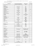
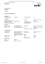
Page 77: ...neral Information Site foul liquor VENDOR OFFER UNITS KSB Model no Vendor to nominate KRTE 80 250 114UG S Service Vendor to nominate Manufacturer Country of manufacture Installation mounting Operation...

Page 78: ...Comply Comply KSB France Comply NBR Comply Comply Comply NBR Comply kg N A Surface preparation Vendor to nominate Priming coat Vendor to nominate Grit blasted coated with Jotacote 412 or equivalent 2...

Page 79: ...uty flowrate per pump and operation configuration nominated are for the purpose of sizing the pump units Pump arrangement should allow standby pump to operate in parallel with duty pump ie in duty dut...

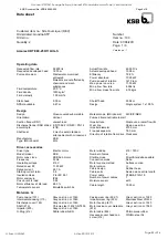
Page 80: ...irection of rotation from drive Clockwise Driver accessories Driver type Electric motor Model make KSB Motor const type KSB Sub motor Frequency 50 Hz Operating voltage 415 V Rated power P2 11 80 kW Ra...

Page 81: ...mer Zinc phosphate synthetic resin Final coating 2 component epoxy resin high solid Color Ultramarine blue RAL 5002 KSB blue Total film thickness approx 150 m Installation parts Scope of supply Pump w...

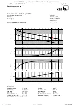
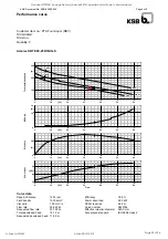
Page 82: ...40 50 60 l s 5 10 kW Power Input Flow Curve data Speed of rotation 1470 rpm Fluid density 1030 kg m Viscosity 1 00 mm s Flow rate 49 003 l s Requested flow rate 52 600 l s Total developed head 15 08 m...

Page 83: ...e data The no load point is not a guarantee point within the meaning of IEC 60034 Load 0 0 25 0 50 0 75 0 100 0 P2 0 00 kW 2 95 kW 5 90 kW 8 85 kW 11 80 kW n 1500 rpm 1491 rpm 1483 rpm 1474 rpm 1465 r...

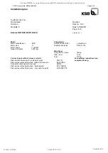
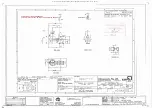
Page 84: ...oot 10 kg Total 170 kg Connect pipes without stress or strain Dimensional tolerances for shaft axis height DIN 747 Dimensions without tolerances middle tolerances to ISO 2768 m Connection dimensions f...

Page 85: ...D SUBMERSIBLE CENTRIFUGAL VENDOR OFFER Service PTA foul liquor Quantity required 2 Country of manufacture VENDOR DOCUMENT NUMBER IW GDSTP 24090 DST 0011 A date C C Ave Ave Max 35 8 L s 10 3 m P2 12 1...

Page 86: ...ation Vendor to nominate Bearing type Ball Roller SS 304 NBR Comply kg Finish coat colour AS 2700 N15 Home Brush Grey Discharge Pedestal Elbow Grit blasted coated with Jotacote 412 or equivalent 2 pac...

Page 87: ...uty assist arrangement if required for instantaneous flows greater than the system duty General Arrangement Drawings Sectionalised Drawings Manufacturer s Pump Specification Sheet Pump Performance Cur...

Page 88: ...rection of rotation from drive Clockwise Driver accessories Driver type Electric motor Model make KSB Motor const type KSB Sub motor Frequency 50 Hz Operating voltage 415 V Rated power P2 7 50 kW Rate...

Page 89: ...er Zinc phosphate synthetic resin Final coating 2 component epoxy resin high solid Color Ultramarine blue RAL 5002 KSB blue Total film thickness approx 150 m Installation parts Scope of supply Pump wi...

Page 90: ...60 l s 2 4 6 kW Power Input Flow Curve data Speed of rotation 1453 rpm Fluid density 1030 kg m Viscosity 1 00 mm s Flow rate 35 893 l s Requested flow rate 33 700 l s Total developed head 12 12 m Req...

Page 91: ...00 1 h Curve data The no load point is not a guarantee point within the meaning of IEC 60034 Load 0 0 25 0 50 0 75 0 100 0 P2 0 00 kW 1 88 kW 3 75 kW 5 63 kW 7 50 kW n 1500 rpm 1485 rpm 1471 rpm 1456...

Page 92: ...kg Claw Foot 10 kg Total 159 kg Connect pipes without stress or strain Dimensional tolerances for shaft axis height DIN 747 Dimensions without tolerances middle tolerances to ISO 2768 m Connection di...

Page 93: ...al STP ST041 Sewage Delivery Amarex KRT Submersible Motor Pump Vendor Manual Q Pulse Id VM362 Active 29 10 2013 Page 93 of 96 KSB Document No KSB 88980 033 Customer Document No IW GDSTP 4A VEN 0110 20...

Page 94: ...al STP ST041 Sewage Delivery Amarex KRT Submersible Motor Pump Vendor Manual Q Pulse Id VM362 Active 29 10 2013 Page 94 of 96 KSB Document No KSB 88980 032 Customer Document No IW GDSTP 4A VEN 0200 20...

Page 95: ...Goodnal STP ST041 Sewage Delivery Amarex KRT Submersible Motor Pump Vendor Manual Q Pulse Id VM362 Active 29 10 2013 Page 95 of 96...

Page 96: ...Goodnal STP ST041 Sewage Delivery Amarex KRT Submersible Motor Pump Vendor Manual Q Pulse Id VM362 Active 29 10 2013 Page 96 of 96...

Reviews: