

Cust. Doc. No.:GDSTP-24090-MAN-0006-P1
KSB Doc. No.:KSB-88980-084
KSB REF No: 88980/ 48
Client
: Thiess
Pty
Ltd
Project
:
Goodna Sewerage Treatment Plant Upgrage [Stage 4A]
P.O. No.
:
GDSTP-24090-CON-0000
Equipment / Tag No. :
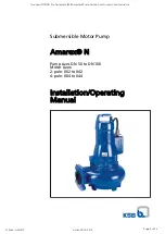
Amenities Pump Station
OPERATING AND
MAINTENANCE
INSTRUCTIONS
K S B A u s t r a l i a P t y L t d
A B N 2 9 0 0 6 4 1 4 6 4 2
A Q u a l i t y E n d o r s e d C o m p a n y A S / N Z I S O 9 0 0 1 : 2 0 0 8
Sales and Service
Phone
: (07)
3436
8600
Fax
: (07)
3436
8699
: ksbqldsales@ksb.com.au
Spares
:
1300 KSB SPARES ( 1300 572 772 )
Issue Date: 8/02/2012
Goodnal STP ST041 Pre Treatment (KSB Amenities Pump Station OM Manual) Vendor Manual
Q-Pulse Id VM372
Active 29/10/2013
Page 1 of 94


