


Summary of Contents for Amarex KRT
Page 77: ......
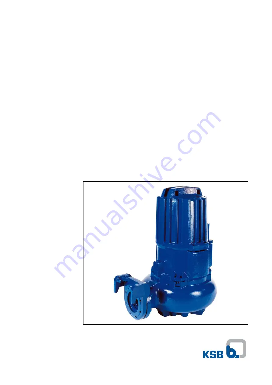
The KSB Amarex KRT pump boasts exceptional performance and reliability. To ensure seamless installation and operation, make the most of our comprehensive "Installation & Operating Manual". Download the manual for free from our website to access detailed instructions and unleash the full potential of your KSB Amarex KRT pump.
Page 77: ......


