background image

3


Transport/Temporary Storage/Disposal

3.1


Transport

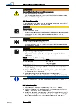
DANGER

Improper transport

Danger to life from falling parts!

Damage to the pump set!

Use the attachment point provided (eyebolt, lifting lug or bail) for attaching
lifting accessories.

Never suspend the pump set by its power cable.

Never use chains or lifting ropes included in KSB's scope of supply for lifting
loads other than the KSB product supplied.

Safely attach transport ropes or chains to the pump and crane.

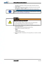
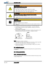
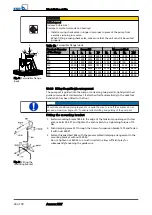
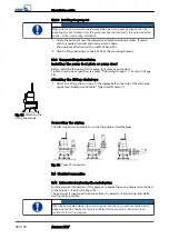
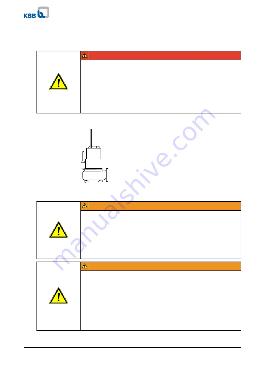
Transport the pump set as shown.

Fig. 1:  Transporting the pump set

Setting down the pump set

WARNING

Placing the pump set on an unsecured and uneven mounting surface

Personal injury and damage to property!

Always place the pump set on a solid and level surface with the pump set in
vertical position and the motor on top.

Only place the pump set on a surface of sufficient load-carrying capacity.

Use appropriate means to secure the pump set against overturning or tipping
over.

Refer to the weights given in the data sheet/name plate.

WARNING

Improper placing of pump sets in vertical/horizontal position

Personal injury and damage to property!

Use appropriate means to secure the pump set against overturning or tipping
over.

Use two lifting devices when handling large pump sets, if possible (using the
attachment point provided on the motor and the discharge nozzle).

Secure power cables against falling.

Use additional supports for the transport holder to secure the pump set against
overturning.

Maintain sufficient safety distance when lifting the pump set.


3 Transport/Temporary Storage/Disposal


Amarex KRT

13 of 78

Summary of Contents for Amarex KRT

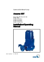
Page 1: ...ubmersible Motor Pump Amarex KRT Pump Sizes DN 40 to DN 300 Motor Sizes 2 pole 5 2 to 55 2 4 pole 4 4 to 65 4 6 pole 4 6 to 50 6 8 pole 10 8 to 35 8 Installation Operating Manual Ident number 01 196 129 ...

Page 2: ...hts reserved Contents provided herein must neither be distributed copied reproduced edited or processed for any other purpose nor otherwise transmitted published or made available to a third party without KSB s express written consent Subject to technical modification without prior notice KSB Aktiengesellschaft Frankenthal 01 09 2010 ...

Page 3: ...or maintenance inspection and installation work 11 2 9 Unauthorised modes of operation 11 2 10 Explosion protection 11 3 Transport Temporary Storage Disposal 13 3 1 Transport 13 3 2 Storage Preservation 14 3 3 Return to supplier 14 3 4 Disposal 15 4 Description of the Pump Set 16 4 1 General description 16 4 2 Designation 16 4 3 Name plate 16 4 4 Design details 16 4 5 Types of installation 17 4 6 ...

Page 4: ...3 Drainage disposal 45 7 4 Dismantling the pump set 45 7 5 Reassembling the pump set 49 7 6 Tightening torques 54 7 7 Spare parts stock 55 8 Trouble shooting 56 9 Related Documents 57 9 1 General assembly drawings 57 9 2 Wiring diagrams 70 9 3 Flamepaths of explosion proof motors 71 9 4 Sectional drawings of the mechanical seal 72 10 EC Declaration of Conformity 74 11 Certificate of Decontaminatio...

Page 5: ...the pump set has been properly drained to eliminate any environmental and health hazards arising from components in contact with the fluid handled Close coupled design Motor directly fitted to the pump via a flange or a drive lantern Hydraulic system The part of the pump in which the kinetic energy is converted into pressure energy Glossary Amarex KRT 5 of 78 ...

Page 6: ... D K D K D K K K K K 200 316 K K K K K K K 200 330 K K K K K K K 200 400 D K D K D 200 401 E K E K K K K K K 250 400 D K D K D K K K K K 250 401 K K K K K K K 300 400 D K D K D K K K K K 300 401 K K K K K K K The manual describes the proper and safe use of this equipment in all phases of operation The name plate indicates the type series and size the main operating data the order number and the or...

Page 7: ...er product literature1 Operating manuals and other product literature describing accessories and integrated machinery components Spare parts lists1 Description of spare parts Supplementary operating manuals1 For example for special accessories 1 5 Symbols Table 3 Symbols used in this manual Symbol Description Conditions which need to be fulfilled before proceeding with the step by step instruction...

Page 8: ...chine damage In conjunction with the signal word CAUTION this symbol indicates a hazard for the machine and its functions 2 2 General This manual contains general installation operating and maintenance instructions that must be observed to ensure safe pump operation and prevent personal injury and damage to property The safety information in all sections of this manual must be complied with This m...

Page 9: ...etc Do not throttle the flow rate on the suction side of the pump set to prevent cavitation damage Consult the manufacturer about any use or mode of operation not described in the data sheet or product literature Only use the respective impeller types in combination with the fluids described below Impeller with cutter impeller type S Suitable for the following fluids Faeces domestic sewage and was...

Page 10: ...sks If required the operator can commission the manufacturer supplier to train the personnel Training on the pump set must always be supervised by technical specialist personnel 2 5 Consequences and risks caused by non compliance with these operating instructions Non compliance with these operating instructions will lead to forfeiture of warranty cover and of any and all rights to claims for damag...

Page 11: ...protective devices Before returning the product to service observe all instructions on commissioning Section 6 1 Page 34 2 9 Unauthorised modes of operation Never operate the pump set outside the limits stated in the data sheet and in this manual The warranty relating to the operating reliability and safety of the supplied pump set is only valid if the equipment is used in accordance with its inte...

Page 12: ...ir work at the flameproof joints must only be performed in accordance with the manufacturer s instructions Repair to the values in tables 1 and 2 of EN 60079 1 is not permitted 2 Safety 12 of 78 Amarex KRT ...

Page 13: ...mp set on a solid and level surface with the pump set in vertical position and the motor on top Only place the pump set on a surface of sufficient load carrying capacity Use appropriate means to secure the pump set against overturning or tipping over Refer to the weights given in the data sheet name plate WARNING Improper placing of pump sets in vertical horizontal position Personal injury and dam...

Page 14: ...pump set at the time of installation Table 5 Ambient conditions for storage Ambient conditions Value Relative humidity 5 to 85 non condensing Ambient temperature 20 to 70 C Store the pump set under dry and vibration free conditions if possible in its original packaging 1 Spray coat the inside wall of the pump casing and in particular the impeller clearance areas with a preservative 2 Spray the pre...

Page 15: ... Fluids posing a health hazard and or hot fluids Hazardous to persons and the environment Collect and properly dispose of flushing liquid and any liquid residues Wear safety clothing and a protective mask if required Observe all legal regulations on the disposal of fluids posing a health hazard 1 Dismantle the pump set Collect greases and other lubricants during dismantling 2 Separate and sort the...

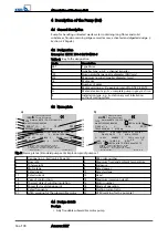
Page 16: ...öFFNEN WARNING DO NOT OPEN WHEN EN ERGIZED AVERTISSEMENT NE PAS OUVRIR SOUS TENSION Mat No 01231886 ZN 3826 M 29 TYPE Amarex KRTK 150 315 164 UG S No 9971235943 000100 Q 300 m3 h H 14 m 2010 TEMP MAX 40 C 0150 kg Motor IP 68 SUBM MAX 30 m CLASS F DKN 160 4 12 3 M No 123456 P2 16 kW 400 690 V 50 Hz cos φ 0 81 1480 min 1 14 3 8 3 A IA IN 4 9 S1 WARNUNG NICHT UNTER SPANNUNG öFFNEN WARNING DO NOT OPEN...

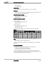
Page 17: ... Table 7 Reinforced bearings Hydraulics size Motor size and number of poles 372 552 554 504 654 D 80 315 X X D 100 315 X X D 150 400 X X X D 150 401 X X D 200 400 X X D 250 400 X X X Drive Three phase asynchronous squirrel cage motor Explosion proof pump sets are supplied with an integrated motor of Ex d IIB type of protection 4 5 Types of installation Two design variants are available depending o...

Page 18: ...ny fluid from flowing back from the casing into the inlet At the rear side of the impeller the shaft 4 enters the casing via the discharge cover 3 The shaft passage through the discharge cover is sealed towards the atmosphere with a shaft seal 8 The shaft runs in rolling element bearings 9 and 10 which are supported by a bearing bracket 5 linked with the pump casing and or discharge cover The pump...

Page 19: ...ments Lifting rope or chain NOTE A separate name plate is included in KSB s scope of supply This name plate must be attached in a clearly visible position outside the place of installation e g at the control panel pipeline or mounting bracket 4 8 Dimensions and weights For dimensions and weights please refer to the general arrangement drawing outline drawing or data sheet of the pump set 4 Descrip...

Page 20: ...me plate data matches the data given in the purchase order and the site system data 5 2 2 Preparing the place of installation Place of installation for stationary models WARNING Installation on foundations which are unsecured and cannot support the load Personal injury and damage to property Make sure the foundation concrete is of sufficient strength min C25 30 to DIN 1045 Make sure the foundation...

Page 21: ...nts All structural work required must have been prepared in accordance with the dimensions stated in the outline drawing general arrangement drawing 5 2 3 Checking the lubricant level The lubricant reservoirs are filled with an environmentally friendly non toxic lubricant at the factory 1 Position the pump set as illustrated 903 03 411 03 903 03 411 03 Fig 4 Checking the lubricant level 2 Unscrew ...

Page 22: ... Page 32 1 Start the pump set and stop it again immediately to determine the motor s direction of rotation 2 Check the direction of rotation Impeller rotation must be anti clockwise seen from the pump mouth end On some pump casings the direction of rotation is marked by an arrow Fig 5 Checking the direction of rotation 3 If the impeller is running in the wrong direction of rotation check the elect...

Page 23: ...C 10 5 3 1 2 Connecting the piping DANGER Impermissible loads acting on the flange of the duckfoot bend have been exceeded Danger to life from leakage of hot toxic corrosive or flammable fluids Do not use the pump as an anchorage point for the piping Anchor the pipelines in close proximity to the pump and connect them without transmitting any stresses or strains Observe the permissible flange load...

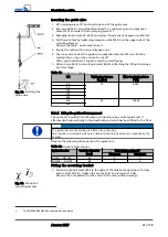
Page 24: ... along two parallel tightly stretched guide wires made of stainless steel It attaches itself automatically to the duckfoot bend which has been fitted to the floor NOTE Should site conditions piping layout etc require the wire to run off the vertical do not exceed a maximum angle of 5 to ensure reliable fitting and guiding of the pump set Fitting the mounting bracket 1 Fasten mounting bracket 894 t...

Page 25: ... P N 50 14 6000 80 100 150 200 250 30 10000 300 5 3 1 4 Fitting the guide rail arrangement The pump set is guided into the sump or tank along two vertical guide rails It attaches itself automatically to the duckfoot bend which has been fitted to the floor NOTE The guide rails are not included in KSB s scope of supply Select guide rail materials which are suitable for the fluid handled or as specif...

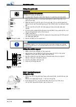
Page 26: ...6 m the scope of supply may include brackets as a middle support for the guide rails The mounting brackets also serve as spacers between the two guide rails Fitting the middle support 1 Measure the inside diameter of the guide rails 2 Expand elastic sleeves 520 39 with clamping sleeves 81 51 39 to the inside diameter of the guide rails by tightening nuts 920 39 3 Slip the guide rails onto the slee...

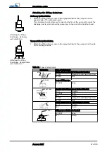
Page 27: ...stallation 1 Attach the lifting chain or rope to the lug eyebolt bail at the pump set on the side of the discharge nozzle Table 13 Types of attachment Illustration Type of attachment 920 26 914 26 Chain attached directly to the motor housing 914 26 Hexagon socket head cap screw 920 26 Nut 59 24 02 Looped lifting rope 59 24 02 Rope 59 24 02 885 59 17 914 26 920 26 Shackle with lifting rope or chain...

Page 28: ...ques Section 7 6 Page 54 Attaching the lifting chain rope 1 Attach the lifting chain or rope to the lug eyebolt on the side of the discharge nozzle see illustration and table Types of attachment Connecting the piping The DIN connection is suitable for connecting rigid or flexible pipes Fig 16 Types of connection 5 4 Electrical connection 5 4 1 Information for planning the control system For the el...

Page 29: ...034 17 DANGER Operation outside the permitted frequency range Explosion hazard Never operate explosion proof pump sets outside the specified range DANGER Incorrect setting of frequency inverter current limit Explosion hazard Set the current limit to max 1 2 times the rated current indicated on the name plate Select the frequency inverter to match the following data Data provided by the manufacture...

Page 30: ...hazards and damage to the pump set Measuring transducers are required for analysing the sensor signals supplied Suitable devices for 230V can be supplied by KSB NOTE Reliable and safe operation of the pump within the scope of our warranty is only possible if the sensor signals are properly analysed as stipulated in these operating instructions All sensors are located inside the pump set and are co...

Page 31: ...istance of 3 to 60 kΩ 5 4 1 4 3 Leakage at the mechanical seal only for pump sets with reinforced bearings The chamber for mechanical seal leakage is equipped with a float switch core identification 3 and 4 The contact maximum 250 V 2 A opens when leakage is detected in the leakage chamber Opening of the contact shall trigger an alarm signal Section 9 2 Page 70 5 4 1 4 4 Bearing temperature As an ...

Page 32: ...tection device in accordance with IEC 947 and local regulations For connection to power supply observe the wiring diagrams Section 9 2 Page 70 in the Annex and the information on planning the control system Section 5 4 1 Page 28 The pump set is supplied complete with power cable Always connect all marked cores DANGER Incorrect connection Explosion hazard The connection point of the cable ends must...

Page 33: ...the cables correctly re affix the markings on the individual cores at the cable ends The pump set does not have an external PE connection risk of corrosion DANGER Incorrect wiring Explosion hazard Explosion proof pump sets installed in a tank must never be retrofitted with an external potential equalisation connection DANGER Touching the pump set during operation Electric shock Make sure that the ...

Page 34: ...le motor is still running down Damage to the pump set Do not re start the pump set before it has come to a standstill Never start up the pump set while the pump is running in reverse The fluid level is sufficiently high CAUTION Pump start up against a closed shut off element Increased vibrations Damage to mechanical seals and bearings Never operate the pump set against a closed shut off element 1 ...

Page 35: ...tactor autotransformer soft starter The limit does not apply to frequency inverter operation CAUTION Re starting while motor is still running down Damage to the pump set Do not re start the pump set before it has come to a standstill Never start up the pump set while the pump is running in reverse 6 2 3 Minimum fluid level DANGER Pump set running dry Explosion hazard Never allow an explosion proof...

Page 36: ...y high density of the fluid handled Motor overload Observe the information on fluid density indicated in the data sheet Make sure the power reserve of the motor is sufficient 6 2 5 Supply voltage DANGER Non compliance with permissible supply voltage tolerances Explosion hazard Never operate an explosion proof pump set outside the specified range The maximum permissible supply voltage deviation is ...

Page 37: ...t freezing Damage to the pump set If there is any danger of frost freezing remove the pump set from the fluid handled and clean preserve and store it Make sure sufficient fluid is available for the operation check run of the pump set 1 For prolonged shutdown periods start up the pump set regularly between once a month and once every three months for approximately one minute This will prevent the f...

Page 38: ...ury from moving parts or escaping fluid As soon as the work is completed re install and or re activate any safety relevant and protective devices NOTE On pumps pump sets older than 5 years we recommend replacing all elastomer seals 6 Commissioning Start up Shutdown 38 of 78 Amarex KRT ...

Page 39: ...mps which handle fluids posing a health hazard WARNING Hot surface Risk of personal injury Allow the pump set to cool down to ambient temperature WARNING Improper lifting moving of heavy assemblies or components Personal injury and damage to property Use suitable transport devices hoisting equipment and lifting tackle to move heavy assemblies or components NOTE Special regulations apply to repair ...

Page 40: ...t has been pulled out of the pump sump and cleaned 1 Inspect the power cable for any visual damage 2 Replace any damaged components by original spare parts The pump set has been pulled out of the pump sump and cleaned 1 Measure the resistance between earth conductor and earth The resistance measured must be less than 1 Ω 2 Replace any damaged components by original spare parts DANGER Defective ear...

Page 41: ... and 11 200 Ω 750 Ω If the specified tolerances are exceeded disconnect the power cable at the pump set and repeat the check inside the motor If the tolerances are exceeded here too the motor section has to be opened and overhauled The temperature sensors are fitted in the stator winding and cannot be replaced Table 17 Resistance of leakage sensor in the motor Measure between terminals Resistance ...

Page 42: ...ring 411 34 again 7 2 2 Lubrication and lubricant change 7 2 2 1 Lubricating the mechanical seal The mechanical seal is supplied with lubricant from the lubricant reservoir 7 2 2 1 1 Intervals Replace the lubricant after every 10 000 operating hours but at least every 3 years Section 7 2 Page 40 7 2 2 1 2 Lubricant quality The lubricant reservoir is filled at the factory with an environmentally fr...

Page 43: ...nd the environment When draining the lubricant take appropriate measures to protect persons and the environment Observe all legal regulations on the disposal of fluids posing a health hazard WARNING Excess pressure in the lubricant reservoir Liquid spurting out when the lubricant reservoir is opened at operating temperature Open the screw plug of the lubricant reservoir very carefully 1 Position t...

Page 44: ... element bearings Lithium soap grease suitable for high temperatures ESSO UNIREX N3 FAG ARCANOL L40 TEXACO HYTEX EP3 DEA Pragon 7 2 2 2 2 Grease quantity Use 60g grease to lubricate the rolling element bearings 7 2 2 2 3 Re lubrication An encapsulated water tight lubricating nipple allows re lubrication of the angular contact ball bearings without opening the pump DANGER Dry running Risk of explos...

Page 45: ...g a health hazard and or hot fluids Hazardous to persons and the environment Collect and properly dispose of flushing liquid and any liquid residues Wear safety clothing and a protective mask if required Observe all legal regulations on the disposal of fluids posing a health hazard 1 Always flush the pump if it has been used for handling noxious explosive hot or other hazardous fluids 2 Always flu...

Page 46: ...ied out 1 Completely disconnect the pump set from the power supply 2 Drain the lubricant 3 Drain the leakage chamber and leave it open for the duration of the disassembly 7 4 3 Dismantling the pump section Dismantle the pump section in accordance with the relevant general assembly drawing Section 9 1 Page 57 7 4 3 1 Removing the back pull out unit 1 Unscrew screwed connection 902 01 and 920 01 and...

Page 47: ...51 D M16 ADS 3 150 251 80 315 D M20 ADS 4 100 315 100 316 150 315 200 315 80 315 D reinforced bearing assembly M24 ADS 5 100 315 150 400 D M24 ADS 5 150 401 200 400 250 400 300 400 7 4 3 2 2 Removing the impeller with cylindrical interference fit with key 1 Unscrew socket head cap screw 914 10 and impeller hub cap 260 2 Remove the impeller using a special impeller mounting and removal device Secti...

Page 48: ...ull the rotating assembly of mechanical seal 433 02 off shaft 210 2 Remove discharge cover 163 from bearing bracket 330 3 Push the stationary seat of mechanical seal 433 02 out of discharge cover 163 7 4 3 3 2 Dismantling the motor end mechanical seal The back pull out unit and the impeller have been removed as described above 1 Remove taper lock ring 515 or circlip 932 03 2 Pull the rotating asse...

Page 49: ...e pump Reassemble the pump set in accordance with the general rules of sound engineering practice Use original spare parts only NOTE Before reassembling the motor section check that all joints relevant to explosion protection flamepaths are undamaged Any components with damaged flamepaths must be replaced Refer to the Flamepaths annex for the position of the flamepaths Always reassemble the pump s...

Page 50: ...at the rotating assembly before fitting the impeller Observe installation dimension A Table 23 Installation dimension A Size Installation dimension A mm 40 250 80 250 100 240 100 250 29 80 251 100 251 150 251 80 315 316 150 315 200 315 316 100 315 316 38 5 100 400 100 401 150 400 150 401 151 401 200 330 200 400 200 401 250 400 401 300 400 401 48 3 7 5 2 2 Fitting the impeller NOTE For bearing brac...

Page 51: ...to the shaft end of the pump set 2 Screw part 1 to the threaded bolt part 2 7 5 2 2 2 Fitting the cutter Fig 30 Fitting the cutter The pump end mechanical seal 433 02 has been installed 1 Slip impeller 230 onto the conical shaft end 2 Insert grooved pin 561 01 into the impeller and place impeller body 23 7 onto the centring hub 3 Screw in impeller screw 914 10 and use a torque wrench to tighten th...

Page 52: ...en hexagon head bolt 901 15 to a torque of 30 Nm 12 Rotate the impeller body to check that the impeller turns smoothly Make sure that the suction cover and impeller do not touch each other 7 5 2 3 Installing the back pull out unit 7 5 2 3 1 Design with axial clearance NOTE After casing wear rings with a radial clearance have been fitted in pump casing 101 they have the required inner diameter and ...

Page 53: ...f the impeller The clearance equals 0 4 0 2 mm measured on the suction side from the outer surface of the impeller vane to the wear plate 5 Insert the complete back pull out unit into the pump casing 6 Evenly tighten screwed connection 920 01 between pump casing and bearing bracket 7 5 3 Reassambling the motor section NOTE Before reassembling the motor section check that all joints relevant to exp...

Page 54: ... the screw plug and joint ring of the lubricant reservoir 2 Tightly screw the testing device into the filler opening for the lubricant 3 Perform the leak test to the above conditions The pressure must not drop during the test period If the pressure does drop check the seals and screwed connections Then perform another leak test 4 Once the leak test has been successful fill in the lubricant Section...

Page 55: ... 24296 Table 26 Quantity of spare parts for recommended spare parts stock9 Part No Description Number of pump sets including stand by pump sets 2 3 4 5 6 and 7 8 and 9 10 and more 80 1 Motor unit 1 1 2 30 834 Cable gland 1 1 2 2 2 3 40 818 Rotor 1 1 2 30 230 Impeller 1 1 1 2 2 3 30 502 Casing wear ring 2 2 2 3 3 4 50 433 01 Mechanical seal motor end 2 3 4 5 6 7 90 433 02 Mechanical seal pump end 2...

Page 56: ...ck the connection of the motor and switchgear if any X Wrong supply voltage Check the mains power supply Check the connection of the power cables X Motor is not running because of lack of voltage Check the electrical installations Contact the energy supplier X X Motor winding or power cable are defective Replace by new original KSB parts or contact KSB X Defective rolling element bearing Contact K...

Page 57: ...nical seal 2 For material variant C1 C2 Hydraulics sizes 40 250 80 250 251 80 315 316 100 240 250 100 251 100 315 316 150 251 150 315 200 315 316 Motor sizes 5 2 6 2 8 2 12 2 17 2 22 2 25 2 23 2 4 4 5 4 7 4 11 4 16 4 19 4 21 4 23 4 29 4 4 6 6 6 9 6 12 6 15 6 19 6 General assembly drawing with motor type DKN 132 160 161 181 and tapered fit impeller type F 9 Related Documents Amarex KRT 57 of 78 ...

Page 58: ...e gland 834 81 54 914 04 412 07 V Upper bearing Motor sizes 5 2 6 2 8 2 4 4 5 4 7 4 4 6 6 6 Upper bearing Motor sizes 22 2 25 2 19 4 21 4 15 6 19 6 Upper bearing Motor sizes 12 2 17 2 23 2 11 4 16 4 23 4 29 4 9 6 12 6 Impeller type D 550 23 914 10 135 412 34 914 12 163 230 101 412 33 914 24 9 Related Documents 58 of 78 Amarex KRT ...

Page 59: ...on 23 7 Impeller body 421 01 Lip seal 69 14 Leakage sensor 433 01 02 Mechanical seal 80 1 Motor unit 441 Shaft seal housing 81 17 End connector 500 02 Ring 81 44 28 Clamping piece 502 Casing wear ring 81 51 Shim 503 Impeller wear ring 81 59 Stator 529 Bearing sleeve 99 17 Dessicant 550 11 23 24 Disc 101 Pump casing 561 01 Grooved pin 113 Intermediate casing 811 Motor housing 9 Related Documents Am...

Page 60: ...mpeller 903 Screw plug 320 Rolling element bearing 904 01 Grub screw 321 01 02 Radial ball bearing 914 02 04 10 15 12 24 26 Hexagon socket head cap screw 322 Radial roller bearing 920 01 26 Nut 330 Bearing bracket 930 28 Safety device 360 Bearing cover 931 Lockwasher 411 03 Joint ring 932 01 02 03 13 Circlip 412 02 03 04 07 15 16 33 34 O ring 9 Related Documents 60 of 78 Amarex KRT ...

Page 61: ...tional drawings of the mechanical seal Hydraulics sizes D 80 315 D 100 315 Motor sizes 37 2 55 2 General assembly drawing with motor type DKN 226 2 pole impeller type D 9 Related Documents Amarex KRT 61 of 78 ...

Page 62: ...02 Mechanical seal 81 18 03 Cable socket 500 04 05 Ring 81 45 Float switch 520 01 Sleeve 81 51 Shim 550 03 23 Disc 81 59 Stator 636 02 Lubricating nipple 101 Pump casing 647 Grease quantity control 135 Wear plate 818 Rotor 163 Discharge cover 834 01 03 Cable gland 230 Impeller 900 20 Screw 320 Rolling element bearing 901 Hexagon head bolt 330 01 Bearing bracket 903 03 04 05 46 Screw plug 360 Beari...

Page 63: ...nal drawings of the mechanical seal 2 For material variant C1 C2 Hydraulics sizes 100 400 401 150 151 400 401 200 330 200 400 401 250 400 401 300 400 401 Motor sizes 23 4 29 4 20 6 26 6 10 8 17 8 21 8 General assembly drawing of pump set with motor type DKN 161 181 and cylindrical interference fit impeller types K E 9 Related Documents Amarex KRT 63 of 78 ...

Page 64: ...g 81 44 28 Clamping piece 529 Bearing sleeve 81 51 Shim 811 Motor housing 81 59 Stator 818 Rotor 99 17 Dessicant 834 Cable gland 101 Pump casing 900 28 Screw 163 Discharge cover 901 20 Hexagon head bolt 260 Impeller hub cap 902 01 Stud 230 Impeller 903 03 05 Screw plug 321 02 Radial ball bearing 914 02 10 04 26 Hexagon socket head cap screw 322 Radial roller bearing 920 01 26 Nut 330 Bearing brack...

Page 65: ... variant C1 C2 Hydraulics sizes 100 400 401 150 151 400 401 200 330 200 400 401 250 400 401 300 400 401 Motor sizes 35 4 50 4 65 4 32 6 40 6 50 6 26 8 35 8 General assembly drawing of pump set with motor type DKN 226 impeller types K E 9 Related Documents Amarex KRT 65 of 78 ...

Page 66: ...rminal 550 01 03 44 Disc 81 51 Shim 811 Motor housing 81 59 Stator 818 Rotor 101 Pump casing 834 03 Cable gland 163 Discharge cover 900 04 20 Screw 230 Impeller 902 01 Stud 260 Impeller hub cap 903 03 05 Screw plug 322 Radial roller bearing 914 01 02 04 05 10 Hexagon socket head cap screw 330 01 02 Bearing bracket 920 01 Nut 321 02 Radial ball bearing 932 01 02 03 20 22 Circlip 411 03 05 Joint rin...

Page 67: ...s sizes D 80 315 D 100 315 D 150 400 D 150 401 D 200 400 D 250 400 D 300 400 Motor sizes 35 4 50 4 65 4 32 6 40 6 50 6 26 8 35 8 General assembly drawing of pump set with motor type DKN 226 4 6 8 pole impeller type D 9 Related Documents Amarex KRT 67 of 78 ...

Page 68: ... views of general assembly drawing of pump set with motor type DKN 226 4 6 8 pole Section Detailed view Cable gland Bearing temperature sensor Lubricant reservoir leakage chamber 9 Related Documents 68 of 78 Amarex KRT ...

Page 69: ...asing 811 Motor housing 135 Wear plate 818 Rotor 163 Discharge cover 834 01 03 Cable gland 230 Impeller 900 04 20 Screw 320 Rolling element bearing 902 01 Stud 322 Radial roller bearing 903 03 04 05 46 Screw plug 330 01 02 Bearing bracket 914 01 02 03 04 05 10 12 24 Hexagon socket head cap screw 360 Bearing cover 920 01 Nut 411 03 04 05 26 46 Joint ring 932 01 02 03 20 Circlip 412 01 02 03 04 07 0...

Page 70: ... 2 2 2 3 3 3 6 6 4 4 4 5 5 5 7 8 9 10 11 U1 U1 V1 V1 W1 W1 U2 U2 V2 V2 W2 W2 PE 21 22 10 11 9 Y U1 V1 W1 U2 V2 W2 Y L1 L1 L2 L2 L3 L3 0W380161 00 11 B2 11 V1 PE U1 W1 21 22 PE 2 3 4 5 1 6 7 8 11 10 9 4 9 10 12 4 PE U2 V2 W2 3 4 F4 21 22 3 4 F5 9 10 B3 R3 R1 R2 W2 U2 U1 W1 V2 3 V1 0W366474 00 U1 U2 V1 V2 W1 W2 PE PE 21 22 10 11 3 4 9 U1 U1 U2 U2 V1 V1 V2 V2 W1 W1 W2 W2 PE PE PE PE 21 22 10 11 3 4 9...

Page 71: ...or sizes Pump set 5 2 6 2 8 2 12 2 17 2 22 2 25 2 23 2 4 4 5 4 7 4 11 4 16 4 19 4 21 4 23 4 29 4 4 6 6 6 9 6 12 6 15 6 19 6 20 6 26 6 1 2 3 1 2 3 Flamepaths 37 2 55 2 35 4 50 4 65 4 32 6 40 6 50 6 26 8 35 8 5 1 4 3 2 1 2 3 4 5 Flamepaths 9 Related Documents Amarex KRT 71 of 78 ...

Page 72: ... 433 01 433 02 OW 309130 05 515 515 Taper lock ring 433 02 Mechanical seal mechanical seal with covered springs HJ Hydraulics sizes 80 251 80 315 100 315 150 315 200 315 316 D 80 315 D 100 251 D 100 315 316 D 150 251 D 150 315 D 200 315 Motor sizes 5 2 6 2 8 2 12 2 17 2 22 2 23 2 25 2 4 4 5 4 7 4 11 4 16 4 19 4 21 4 23 4 29 4 4 6 6 6 9 6 12 6 15 6 19 6 433 01 Mechanical seal bellows type mechanica...

Page 73: ... 4 50 4 65 4 20 6 26 6 32 6 40 6 50 6 10 8 17 8 21 8 26 8 35 8 433 01 Mechanical seal bellows type mechanical seal 433 01 932 03 433 02 550 44 550 03 550 03 Disc 932 03 Circlip 433 02 Mechanical seal bellows type mechanical seal Disc 550 44 412 17 O ring 433 02 Mechanical seal mechanical seal with covered springs HJ 433 02 A 9 Related Documents Amarex KRT 73 of 78 ...

Page 74: ... EC The manufacturer also declares that the following harmonised international standards were applied ISO 12100 1 A1 ISO 12100 2 A1 ISO 14121 1 EN 809 A1 EN 60034 1 EN 60034 5 A1 Person authorised to compile the technical file Thomas Pensler Head of Product Development Waste Water Pumps KSB Aktiengesellschaft Turmstraße 92 06110 Halle The EC Declaration of Conformity was issued in on Place date Na...

Page 75: ... outside prior to dispatch placing at your disposal On seal less pumps the rotor has been removed from the pump for cleaning No special safety precautions are required for further handling The following safety precautions are required for flushing fluids fluid residues and disposal We confirm that the above data and information are correct and complete and that dispatch is effected in accordance w...

Page 76: ...kage monitoring 31 Level control 29 Lubricant Intervals 40 Quality 42 Quantity 43 M Maintenance work 40 Measuring the insulation resistance 40 Mechanical seal 40 72 Mechanical seal leakage 31 Minimum fluid level 36 Misuse 10 O Operating limits 8 Order number 6 Other applicable documents 7 Overload protection device 29 P Partly completed machinery 6 Permissible flange loads 24 Piping 24 Place of in...

Page 77: ......
Page 78: ...KSB Aktiengesellschaft P O Box 200743 06008 Halle Saale Turmstraße 92 06110 Halle Germany Tel 49 345 4826 0 Fax 49 345 4826 4699 www ksb com 2553 86 4 10 ...

Reviews: