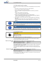
5 Installation at Site
26 of 72
Amarex N
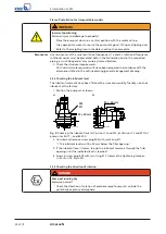
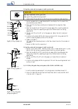
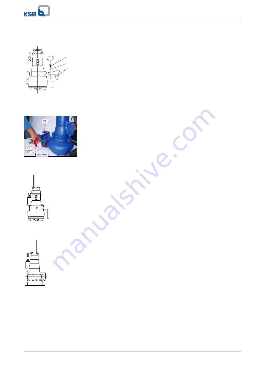
5.3.1.6 Preparing the pump set
Fastening the claw for guide wire, single guide rail and guide hoop arrangement
2563:103
732
550.35
914.05
17 Nm
Fig. 13:
Fastening the claw
for guide wire, single guide
rail and guide hoop
arrangement
1.
Fasten claw 723 with screw 914.05 and disc 550.35 to the discharge flange (see
drawing). Tighten the screw to a torque of 17 Nm.
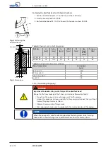
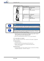
Fastening the claw for guide rail arrangements with 2 guide rails
Fig. 14:
Fastening the claw
for guide rail arrangements
with 2 guide rails
1.
Fasten claw 732 with screws 920 and discs 550 to the discharge flange (see
illustration). Tighten the screw to a torque of 70 Nm.
2.
Fit profile joint 410 in the groove of the claw.
This will seal the duckfoot bend/pump connection.
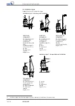
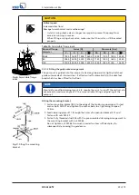
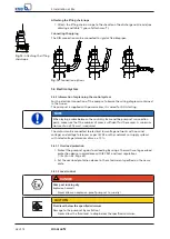
Attaching the lifting chain/rope
UG1274774
Attaching the lifting
chain/rope - stationary
wet installation
Stationary wet installation
1.
Attach the lifting chain with shackle or the lifting rope to the recess in the pump
handle opposite the discharge nozzle. This attachment point achieves a forward
inclination of the pump set towards the discharge nozzle, which allows the pump
claw to hook onto the duckfoot bend.
UG1274785
Attaching the lifting
chain/rope - transportable
wet installation
Transportable wet installation
1.
Attach the lifting chain with shackle or the lifting rope to the recess in the pump
handle on the discharge nozzle side of the pump set. This attachment point
achieves an upright position of the pump set.
Summary of Contents for Amarex N
Page 62: ...9 Related Documents 62 of 72 Amarex N 9 2 2 Version ULG Fig 33 Wiring diagram for version ULG...
Page 70: ......
Page 71: ......

