7 Servicing/Maintenance
50 of 72
Amarex N
2563:114
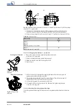
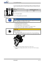
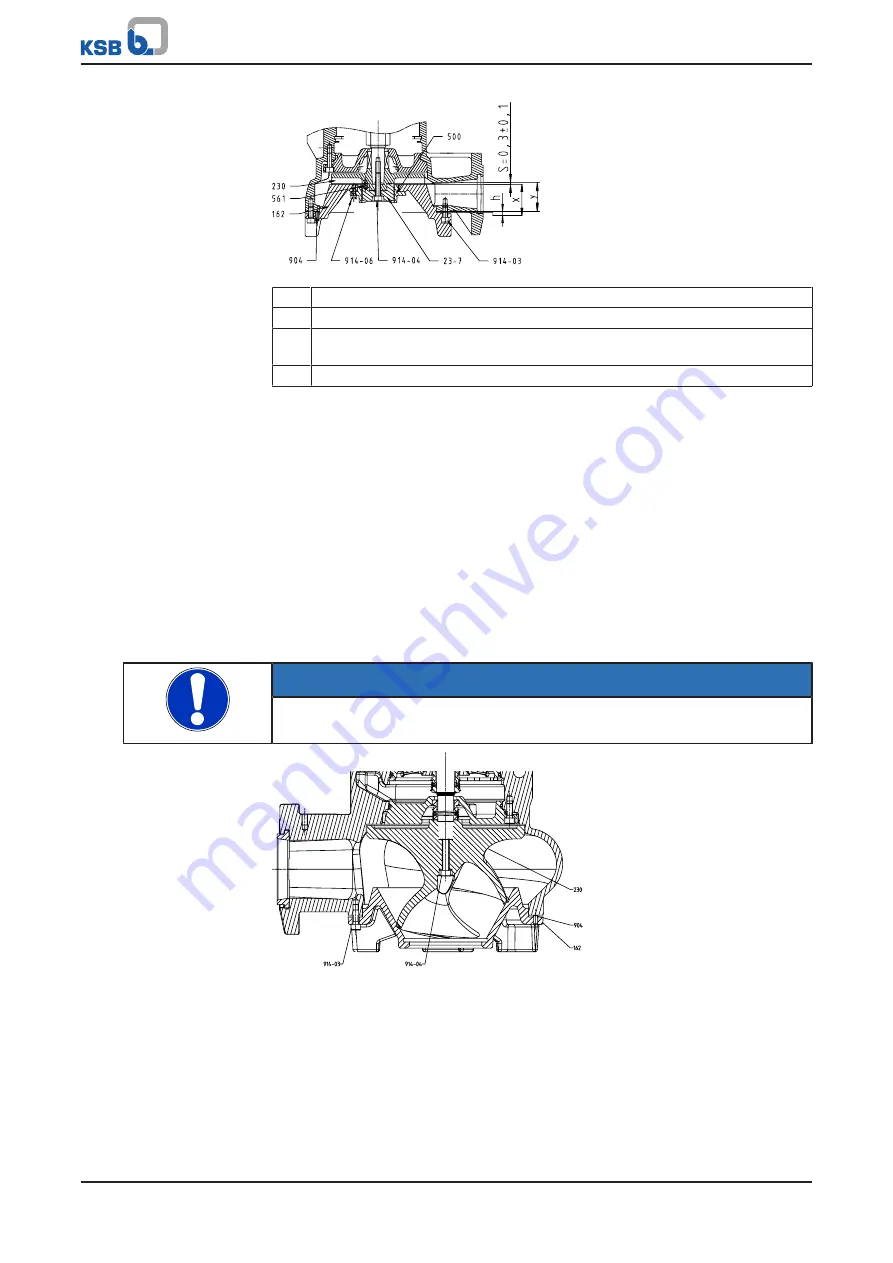
Fig. 26:
Adjusting impeller type S
h
Distance between suction cover and pump casing
s
Clearance gap between suction cover and impeller vanes
x
Distance between the upper side of the suction cover and the mounting holes
of the suction cover
y
Distance between the bottom of the pump casing and the impeller vanes
7.
Measure dimension x on the suction cover
Dimension x is the distance between the upper side of the suction cover and the
mounting holes of the suction cover.
8.
Measure dimension y between the pump casing and the impeller vanes.
Dimension y is the distance between the bottom of the pump casing and the
impeller vanes.
9.
Use screws 904 to set dimension h (h = x + s - y),
where s (0.3 + -0.1) is the clearance between the suction cover and the impeller
vanes.
10.
Tighten the suction cover with screws 914.03.
11.
Rotate the impeller body to check that the impeller turns smoothly.
Make sure that the suction cover and impeller do not touch each other.
7.5.2.2.2 Fitting impeller type D
NOTE
For bearing brackets with tapered fit make sure that the tapered fit of impeller and
shaft is undamaged and installed free from grease.
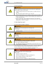
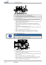
2563:127
Fig. 27:
Fitting impeller type D
1.
Slide impeller 230 onto the shaft end and fasten it with impeller screw 914.04.
2.
Then, remove the impeller screw again.
3.
Screw in an M8 x 100 eyebolt (not included in KSB's scope of supply) instead of
the impeller screw.
4.
Push on suction cover 162 until it rests against the impeller.
5.
Suspend the pump set by the eyebolt (not included in KSB's scope of supply).
6.
Screw in levelling screws 904 until they abut against the pump casing.
7.
Carefully lower down the pump set again.
Summary of Contents for Amarex N
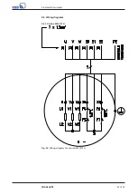
Page 62: ...9 Related Documents 62 of 72 Amarex N 9 2 2 Version ULG Fig 33 Wiring diagram for version ULG...
Page 70: ......
Page 71: ......


