
2 Safety
7 of 50
8417.8/20-EN
2 Safety
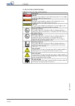
!
DANGER
All the information contained in this section refers to hazardous situations.
In addition to the present general safety information the action-related safety
information given in the other sections must be observed.
2.1 General
▪
This operating manual contains general installation, operating and maintenance
instructions that must be observed to ensure safe operation of the system and
prevent personal injury and damage to property.
▪
Comply with all the safety instructions given in the individual sections of this
operating manual.
▪
The operating manual must be read and understood by the responsible specialist
personnel/operators prior to installation and commissioning.
▪
The contents of this operating manual must be available to the specialist
personnel at the site at all times.
▪
Information and markings attached directly to the product must always be
complied with and kept in a perfectly legible condition at all times. This applies
to, for example:
– Manufacturer
– Type designation
– Nominal pressure
– Nominal size
– Year of construction
– Valve body material
▪
The operator is responsible for ensuring compliance with all local regulations not
taken into account.
▪
The design, manufacture and testing of the valve are subject to a QM system to
DIN EN ISO 9001 as well as the current European Pressure Equipment Directive.
▪
Bear in mind that valves exposed to creep-rupture conditions have a limited
service life and have to meet the applicable regulations stipulated in the
technical codes.
▪
In the case of customised special variants, further restrictions may apply with
regard to the operating mode and service life. Refer to the relevant sales
documentation for applicable limitations.
▪
The operator is responsible for ensuring compliance with all local regulations not
taken into account.
▪
The operator is responsible for any eventualities or incidents which may occur
during installation performed by the customer, operation and maintenance.
2.2 Intended use
▪
Only operate valves which are in perfect technical condition.
▪
Do not operate the valve in partially assembled condition.
▪
Only use the valve for fluids specified in the product literature. Take the design
and material variant into account.
▪
Only operate the valve within the operating limits described in the other
applicable documents.
▪
The valve's design and rating are based on predominantly static loading in
accordance with the codes applied. Consult the manufacturer if the valve is
subjected to dynamic loads or any other additional influences.
▪
Consult the manufacturer about any other modes of operation not described in
the product literature.
▪
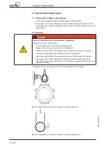
Do not use the valve as a foothold.
Summary of Contents for BOAX-B
Page 1: ...Butterfly Valve Installation Operating Manual ...
Page 49: ......


