5 Installation at Site
23 of 44
Hya-Duo D FL
5.6.4 Connecting the limit switches (remote ON/OFF)
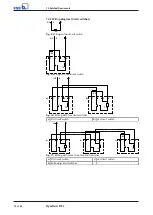
1. Connect one or several limit switches in accordance with the wiring diagram
(limit switches). When connecting several limit switches, connect the
terminating resistor behind the last limit switch. (
The terminals for connecting limit switches (remote ON/OFF) are marked in the
switchgear and controlgear assembly. A terminating resistor of 10 kΩ is connected at
the terminals. The relay for broken wire monitoring and the relay for short-circuit
monitoring analyse the following resistance values:
▪
10 kΩ: no fault
▪
> 10.3 kΩ: broken wire
▪
< 300 Ω: short circuit
▪
1 kΩ: pump start through actuation of limit switch
5.6.5 Connecting the dry running protection device
ü
The original operating manual of the dry running protection device is on hand.
1. Fit the dry running protection device in accordance with the supplied original
operating manual. Connect it in the control unit in accordance with the supplied
original operating manual.
5.6.6 Connecting the volt-free contacts
1. Establish the connection in accordance with the wiring diagram. The terminals
are marked in the switchgear and controlgear assembly.
2. If fault information of volt-free individual fault messages is to be transmitted as
a volt-free general fault message, loop through the volt-free individual fault
messages.
Volt-free contacts are provided for the following messages:
▪
General fault message
– Motor protection warning
– No control voltage
– Short circuit / broken wire
– Mains fault
– Excessive pump temperature
▪
General fault message
– Accumulator overflowing
– Lack of water / dry running
– Switch position of manual-automatic selector switch
5.6.7 Connecting electrical accessories
1. Connect the electrical accessories in accordance with the wiring diagram.

