background image

8 Servicing/Maintenance

31 of 44

Hya-Duo D FL

8 Servicing/Maintenance

8.1 General information/safety regulations

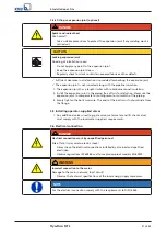
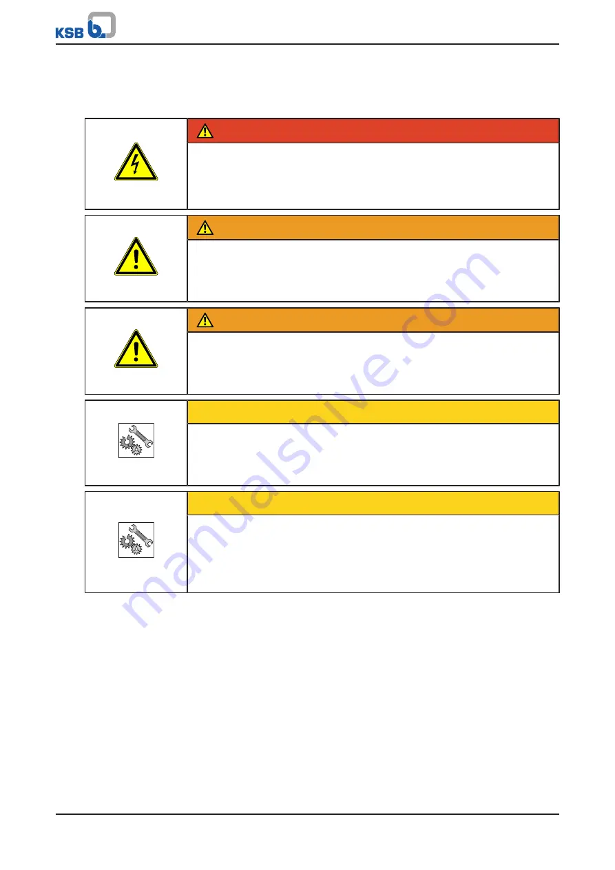
 DANGER

Unintentional start-up of the fire-fighting system

Danger to life!

De-energise the fire-fighting system for any repair work or servicing work.

Secure the fire-fighting system against unintentional start-up.

 WARNING

Improper lifting/moving of heavy assemblies or components

Personal injury and damage to property!

Use suitable transport devices, lifting equipment and lifting tackle to move
heavy assemblies or components.

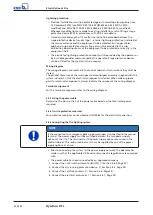
 WARNING

Work on the fire-fighting system by unqualified personnel

Risk of injury!

Always have repair work and maintenance work performed by specially trained,
qualified personnel.

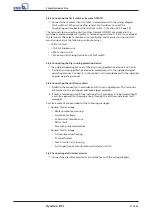
CAUTION

Use after event of fire / failure

Malfunction; functions not working!

Completely check the fire-fighting system after it has been operated in an
event of fire.

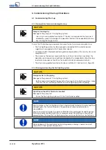
CAUTION

Incorrectly serviced fire-fighting system

Function of fire-fighting system not guaranteed!

Service the fire-fighting system regularly.

Create a maintenance schedule. Observe the information on lubricant, shaft
seal and coupling of the pump sets.

The operator ensures that maintenance, inspection and installation are performed by
authorised, qualified specialist personnel who are thoroughly familiar with the
manual.

Observe the safety instructions and information.

For any work on the pump (set) observe the operating manual of the pump (set).

In the event of damage you can always contact KSB- KSB Service .

A regular maintenance schedule will help avoid expensive repairs and contribute
to trouble-free, reliable operation with a minimum of maintenance expenditure
and work.

Never use force when dismantling and reassembling the equipment.

8.2 Inspection contract

For all inspection work and servicing work to be carried out at regular intervals we
recommend taking out the KSB inspection contract. Contact your service partner for
details.

Summary of Contents for Hya-Duo D FL Series

Page 1: ...Fire fighting System Hya Duo D FL From series 2014w33 Installation Operating Manual...

Page 2: ...tents provided herein must neither be distributed copied reproduced edited or processed for any other purpose nor otherwise transmitted published or made available to a third party without the manufac...

Page 3: ...General description 14 4 2 Product information as per Regulation No 1907 2006 REACH 14 4 3 Designation 14 4 4 Name plate 14 4 5 Design details 14 4 6 Configuration and function 16 4 7 Noise characteri...

Page 4: ...al mode 29 7 2 2 Functional check run 29 7 3 Functions 30 7 3 1 Automatic switchover duty system and back up system 30 7 3 2 Dry running protection 30 7 3 3 Temperature monitoring 30 8 Servicing Maint...

Page 5: ...d health hazards arising from components in contact with the fluid handled DIN 14462 The fire fighting systems break tank package booster sets for fire fighting must comply with the German standard fo...

Page 6: ...ed machinery To install partly completed machinery supplied by KSB refer to the sub sections under Servicing Maintenance 1 3 Target group This operating manual is aimed at the target group of trained...

Page 7: ...amage to the machine and its functions Explosion protection This symbol identifies information about avoiding explosions in potentially explosive atmospheres in accordance with EU Directive 2014 34 EU...

Page 8: ...ble documents Only operate the fire fighting system in perfect technical condition Do not operate partially assembled fire fighting systems Only use the fire fighting system to handle the fluids descr...

Page 9: ...tions shall be complied with Accident prevention health regulations and safety regulations Explosion protection regulations Safety regulations for handling hazardous substances Applicable standards di...

Page 10: ...ave been drained When taking the fire fighting system out of service always adhere to the procedure described in the operating manual Decontaminate fire fighting system which handle fluids posing a he...

Page 11: ...weights centre of gravity and fastening points Use suitable and permitted transport equipment e g crane forklift or pallet truck Attach the fire fighting system to crane lifting tackle as shown or use...

Page 12: ...ient condition Value Relative humidity 50 maximum Ambient temperature 0 C to 40 C Frost free Well ventilated 3 4 Return to supplier 1 Drain the fire fighting system as per operating instructions 2 Flu...

Page 13: ...e fire fighting system Collect greases and other lubricants during dismantling 2 Separate and sort the pump materials e g by Metals Plastics Electronic waste Greases and other lubricants 3 Dispose of...

Page 14: ...4 Name plate 1 2 4 3 6 5 8 7 Johann Klein Stra e 9 Deutschland 67227 Frankenthal KSB SE Co KGaA Hmax 88 4 m Qmax 22 5 m h Made in Germany 29133689 ZNI1448 P Hya Duo D FL 2 1506 B 2019w04 400 V 3 10 0...

Page 15: ...tch or remote ON OFF monitored for broken wires and short circuit Circuit diagram to VDE and parts list for electric parts Indication via indicator lamps Colour LED indicating lack of water red Colour...

Page 16: ...t start up pressure pE the pump sets are started up via the pressure switch When consumption decreases again the pump sets are stopped as a function of pressure after the set after run time up to 10 m...

Page 17: ...f valves Discharge side direct flow membrane type accumulator Pressure switch on the discharge side Pressure gauge Base frame Temperature sensor Control unit Two power supply connections Two motor pro...

Page 18: ...uarters and or sleeping quarters NOTE Observe the installation requirements to DIN 14462 Before beginning with the installation check the following All structural work required has been checked and pr...

Page 19: ...oncrete has set firmly The foundation is level 1 Align the fire fighting system horizontally Standard design If necessary insert shims wedges or other supports under baseplate sections designed to con...

Page 20: ...ng to the distribution lines on the inlet side and discharge side 5 4 1 Connecting the by pass line CAUTION By pass line not connected Flooding of installation room Guide the by pass line from the sol...

Page 21: ...ng free of twist or distortion Never use the expansion joint to compensate for misalignment or mismatch of the piping 3 Evenly tighten the bolts crosswise The ends of the bolts must not protrude from...

Page 22: ...and controlgear assembly supplied with the system includes a list of the electrical components installed When ordering spare parts for electrical components always indicate the number of the wiring d...

Page 23: ...rotection device is on hand 1 Fit the dry running protection device in accordance with the supplied original operating manual Connect it in the control unit in accordance with the supplied original op...

Page 24: ...er or the office for industrial safety and product safety The dry running protection device has been installed Section 5 6 5 Page 23 6 1 2 Priming and venting the fire fighting system CAUTION Foreign...

Page 25: ...e the direction of rotation to the arrow indicating the direction of rotation on the motor If the direction of rotation does not match interchange the phases at the motor terminal board 8 Set the manu...

Page 26: ...ess for operation 6 1 5 Checklist for commissioning start up Table 6 Checklist Steps to be carried out Action Done 1 Read the operating manual 2 Compare the power supply data against the name plate da...

Page 27: ...6 2 1 Frequency of starts To prevent high temperature increases in the motor and excessive loads on the pump motor seals and bearings the frequency of starts shall not exceed the following number of s...

Page 28: ...ump in manual mode Size Minimum flow rate per pump l h Movitec 2B 200 Movitec 4B 400 Movitec 6B 600 Movitec 10B 1100 Movitec 15B 1600 Movitec 25B 2800 Movitec 40B 4600 Movitec 60B 6100 Movitec 90B 850...

Page 29: ...mode is reserved for emergencies Continuous manual operation would lead to waste of energy and water and cause the fluid handled and or the pump sets to overheat A manual automatic selector switch fo...

Page 30: ...oster system no longer ready for operation Failure phase monitoring Switchover back to duty system Pressure booster system no longer ready for operation Failure phase monitoring Motor protection switc...

Page 31: ...ed in an event of fire CAUTION Incorrectly serviced fire fighting system Function of fire fighting system not guaranteed Service the fire fighting system regularly Create a maintenance schedule Observ...

Page 32: ...ge pressure of the accumulator with the recommended data Section 8 4 Page 33 Check the rolling element bearings for running noises Vibrations noise and an increase in current input occurring during un...

Page 33: ...arge pressure 3 bar Example 1 pE 5 bar 5 bar 0 9 4 5 bar At a start up pressure of 5 bar the pre charge pressure of the accumulator must be set to 4 5 bar Example 2 pE 2 bar 2 bar 0 8 1 6 bar At a sta...

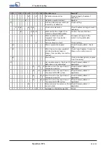
Page 34: ...nical seal H Motor pump overheated I Motor protection switch triggered Yellow indicator lamp is on J Pump does not stop K Pump starts too often more than 30 starts per hour L Broken wire and short cir...

Page 35: ...Check fuse Main fuse on owner supplied distribution board loose or blown fuses possibly too small or too fast Check fuses Replace if necessary Measure the motor current Phase failure Check individual...

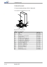
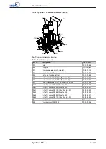
Page 36: ...91 Pressure gauge discharge side 00 401 413 741 Solenoid valve 1 2 01 164 282 742 Lift check valve 1 Movitec 2 4 01 149 253 742 Lift check valve 1 1 4 Movitec 6 01 149 254 742 Lift check valve 1 1 2 M...

Page 37: ...e make Reflex 01 079 765 747 Swing check valve DN 65 Movitec 25 01 086 243 747 Swing check valve DN 80 Movitec 40 01 056 931 747 Swing check valve DN 100 Movitec 60 90 01 087 142 746 1 Butterfly valve...

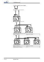
Page 38: ...3 5 4 1k 4 X2 Fig 9 Wiring with one limit switch a b 1 X2 4 2 3 5 4 1k 1 R2 2 3 4 1k Fig 10 Wiring with two limit switches a First limit switch b Last limit switch 1 X2 4 2 3 5 4 1k 1 2 3 4 1k 1 R2 2...

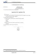
Page 39: ...ions of the following Directives as amended from time to time Pump set Machinery Directive 2006 42 EC The manufacturer also declares that the following harmonised international standards have been app...

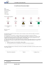
Page 40: ...ng ring carrier plain bearing inner rotor has been removed from the pump and cleaned In cases of containment shroud leakage the outer rotor bearing bracket lantern leakage barrier and bearing bracket...

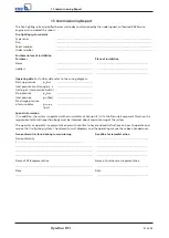
Page 41: ...tch Stop pressure pA bar Inlet pressure pinl bar Pre charge pressure of accumulator ppre charge bar Special information If in addition the system is operated with accumulators of Groups III IV to the...

Page 42: ...starts 27 Functions Automatic switchover duty system and back up system 30 I Installation 14 Installation at site 18 Intended use 8 K Key to safety symbols markings 7 L LED display 29 List of componen...

Page 43: ......

Page 44: ...KSB SE Co KGaA Johann Klein Stra e 9 67227 Frankenthal Germany Tel 49 6233 86 0 www ksb com 1968 85 06 EN 01345700...

Reviews: