


5 Installation at Site
12 of 20
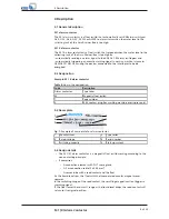
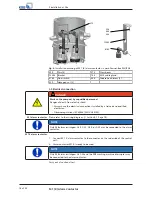
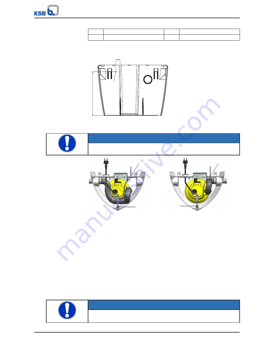
M 1 (K) Alarm Contactor
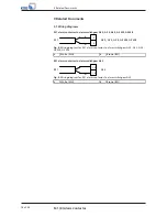
900
Self-tapping screw
M1
Drilled hole, Ø 2.8 mm
M2
Drilled hole, Ø 16 mm
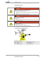
1.
Screw float switch 81-45 to bracket 732.01.
2.
Fit the bracket on pump 655 (M1 hole) using the fasteners supplied.
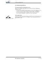
27
2
8
0
M2
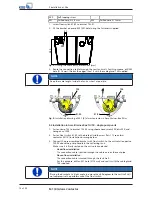
Fig. 3:
Drilling the cable entry; dimensions [mm]
3.
Route the connection cable through the rear tank wall. For this purpose, drill M2
hole (Ø 16 mm). (Debur the edges.) Seal it with the cable gland 734 supplied.
NOTE
Keep the cable length inside the tank as short as possible.
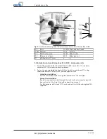
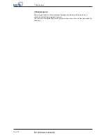
734
734
81-45
81-45
Fig. 4:
Installation drawing of M 1 (K) alarm contactor in Ama-Drainer-Box Mini
5.3 Installation in Ama-Drainer-Box 1U/1B - single-pump units
1.
Fasten clamp 733 to bracket 732.02 using cheese head screw 900, disc 550, and
hexagon nut 920.
2.
Fasten float switch 81-45 to the bracket (width across flats 17); see alarm
contactor M1 (K) installation drawing below.
3.
Connect the pre-assembled bracket with float switch to the anti-rotation device
720.02 above the pump handle in the collecting tank.
Make sure it is firmly seated on the anti-rotation device!
–
Underfloor installation
The
connection cable is pulled through the cable duct or the vent pipe.
–
Above-floor installation
The
connection cable is routed through the tank wall.
For this purpose, drill an M1 hole (Ø 16 mm) and seal it with the cable gland
734 supplied.
NOTE
Placing the bracket at a slight angle (no more than 30 degrees to the vertical) will
not compromise the performance of the float switch.


