3
Cable gland
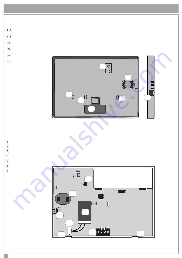
FIGURE 1 - FRONT VIEW OF THE KEYPAD BASE
FIGURE 2 - PARTS DESCRIPTION AND PCBA TERMINALS
C010
k18121PP
8Ω
4
6
2
3
5
7
1
Note
: DO NOT REMOVE PCB AND DISPLAY FROM PLASTIC SUPPORT
USB connector
+ A B - : Connection clamps on KSI-BUS
Anti opening / tamper switch (Tamper)
Loudspeakers contact
Snap fingers
Battery Connector
Battery Pack
A B
4
4
1
6
5
2
3
7
DISPLAY
USB connector
PARTS DESCRIPTION
Easy open hole to be opened to Built-In installation on DIN 530 box
Eyelets for 60mm-screws-distance boxes
Place a wall mount screw to enable anti opening and removal tamper
Speaker


