background image


19


6.5 Press “Update” to save new parameters and reboot. 


Summary of Contents for LR-201-DIO

Page 1: ...1 LoRa Interface Converter DI DO Controller LR 201 E LR 201 S LR 201 U LR 201 DIO User Manual Edition 201807v1 0 http www tcpipweb com this document subject to change without prior notice...

Page 2: ...2 Ethernet LAN Port 11 2 5 3 Serial Port RS 232 RS 422 485 11 2 5 4 2 DI 2 DO port 11 2 5 5 Reset Button 11 2 6 LED Indicators 11 3 Wiring Architecture 12 3 1 Ethernet LoRa air LoRa Serial Interface M...

Page 3: ...cy bands at 862 932 MHz The gateway has been built with the module integrated many RF functions and PA to make the maximum output power up to 20dBm LoRa Interface Gateways are packaged in a plastic ca...

Page 4: ...emperature humidity and air quality information Electricity facilities measurement and management such as smart street lighting Agriculture and animal husbandry monitoring and management 1 2 Packaging...

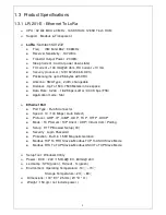
Page 5: ...free space Data Rate 0 244 18 2K bps LoRa 300 K bps FSK Application mode Star Ethernet Port Port Type RJ 45 Connector Speed 10 100 Mbps Auto Detect Protocol ARP IP ICMP UDP TCP HTTP DHCP Mode TCP Serv...

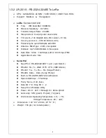
Page 6: ...able Distance Up To 5000 Meters in free space Data Rate 0 244 18 2K bps LoRa 300 K bps FSK Application mode Star Serial Port No of Port RS 232 422 485 1 port auto Detect RS 232 Rx Tx GND RTS CTS DB9 f...

Page 7: ...changeable Distance Up To 5000 Meters in free space Data Rate 0 244 18 2K bps LoRa 300 K bps FSK Application mode Star USB Port No of Port USB 1 port Connector USB type B Chipset Silicon Laboratories...

Page 8: ...Up To 5000 Meters in free space Data Rate 0 244 18 2K bps LoRa 300 K bps FSK Application mode Star Digital I O Digital Input 2 3000VDC Isolation Protect Active High Active Low Selectable Dry contact L...

Page 9: ...ws 2 1 LR 201 E Ethernet To LoRa 2 2 LR 201 S RS 232 422 485 To LoRa LED Indicators RS 422 485 RS 232 DC IN Power Outlet Antenna Ethernet LAN port Reset button LED Indicators DC IN Power Outlet Antenn...

Page 10: ...10 2 3 LR 201 U USB To LoRa 2 4 LR 201 DIO LoRa to Digital I O Controller LED Indicators Reset button Antenna USB port LED Indicators Reset button Antenna DC IN Power Outlet 2 DI 2 DO port...

Page 11: ...l Port RS 232 RS 422 485 Connecting the Serial Port Cable from the LoRa Gateway to the Serial Interface device Follow the parameter setup procedures to configure the converter see the following chapte...

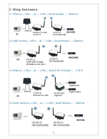
Page 12: ...3 1 Ethernet LoRa air LoRa Serial Interface Machine 3 2 USB Interface LoRa air LoRa Serial Interface Machine 3 3 Ethernet LoRa air LoRa Serial DI DO Interface DI DO 3 4 Serial Interface LoRa air LoRa...

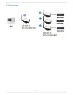
Page 13: ...13 3 5 Star topology...

Page 14: ...ory default Spreading Factory for reference only not exactly to real device Uart Baud Rate bps 9600 Parity None Date Bit 8 Stop Bit 1 Lora Frequency Hz 915500000 Spreading Factor 9 Bandwidth kHz 125 T...

Page 15: ...to onnect with the RS 232 port A crosslink RS 232 adaptor is necessary 5 1 3 For USB to LoRa model pull off USB plug from NB PC USB host 5 1 4 For DI DO to LoRa model pull off power plug 5 2 Poke Dip...

Page 16: ...ing devices Encryption is optional for security purpose 5 10 Interface discard this function temporarily 5 11 Press Write button to write parameters back to device 5 12 Pull off power plug or USB plug...

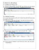
Page 17: ...re Connection 6 2 1 Connect host computer and LR 201 E to Switch Hub with RJ45 Ethernet cable 6 2 2 Power on LR 201 E 6 2 3 Click the icon of Binocular as Refresh it will search and show up the IP of...

Page 18: ...rter s IP to Web browser Configuration pate will show up Click Login without password 6 4 LoRa module only use port 1 with default socket 501 Please don t change the parameters inside the red square P...

Page 19: ...19 6 5 Press Update to save new parameters and reboot...

Page 20: ...st follow above LoRa setting procedure This device without WEB interface settings 9 LoRa to DI DO Modbus codes 9 1 Digital Output 9 1 1 port 1 ON 01 06 00 00 00 01 9 1 2 port 1 OFF 01 06 00 00 00 00 9...

Page 21: ...N 4 DTR PIN 5 GND PIN 6 DSR PIN 7 RTS PIN 8 CTS PIN 9 X RS 232 Wiring Diagram Serial Device Converter 2 RX 3 TX 3 TX 2 RX 5 GND 5 GND 7 RTS 8 CTS 8 CTS 7 RTS RS 422 485 Pin Assignment The pin assignme...

Reviews: