background image


- 1 - 

INDEX FOR KSM-Multistoker 575-50 WITH PCT 300. Version 1-2011 


1.0 Introduction. ........................................................................................................................................ 5


2.0 Fuel. .................................................................................................................................................... 6


2.1 Wood Pellets ................................................................................................................................... 6


2.2 Grain................................................................................................................................................ 6


2.3 Alternative Fuels. ............................................................................................................................ 6


2.4 Fire Wood. ...................................................................................................................................... 6


3.0 Control Panel....................................................................................................................................... 7


4.0 Control Layout and Functioning ......................................................................................................... 8


4.1 Opstart. ............................................................................................................................................ 8


4.2 ALARM .......................................................................................................................................... 8


4.3 Steps. ............................................................................................................................................... 8


4.4 Pause. .............................................................................................................................................. 9


4.5 Pause Firing..................................................................................................................................... 9


4.6 Programmes. ................................................................................................................................... 9


5.0 The Control Panel Buttons and Their Functions ............................................................................... 10


5.1 Stop Screw. ................................................................................................................................... 10


5.2 Start Screw. ................................................................................................................................... 10


5.3 Arrow up/down. ............................................................................................................................ 10


5.4 Menu. ............................................................................................................................................ 10


5.5 Starting Up. ................................................................................................................................... 10


6.0 Operation. .......................................................................................................................................... 11


6.1 Main Screen. ................................................................................................................................. 11


6.2 Changing the settings. ................................................................................................................... 11


6.3 Languages. .................................................................................................................................... 11


6.4 Fuel type. ....................................................................................................................................... 11


6.5 Boiler temperature......................................................................................................................... 12


6.6 Pause period. ................................................................................................................................. 12


6.7 Solid Wood temperature. .............................................................................................................. 12


6.8 Man/Auto. ..................................................................................................................................... 13


6.9 Manual operation. ......................................................................................................................... 13


6.10 Ashscrew. .................................................................................................................................... 14


6.11 Moving Floor ON........................................................................................................................ 14


6.12 Moving floor OFF. ...................................................................................................................... 14


6.13 Transport screw ON .................................................................................................................... 15


6.14 Transport screw OFF. ................................................................................................................. 15


Summary of Contents for KSM-Multistoker 575-50

Page 1: ...Instructions KSM Multistoker 575 50 Producer KSM Stoker Make money by installing K S Stoker Næssundvej 440 7960 Karby DK Tlf 45 97761072 www ksm stoker dk Email Mail ksm stoker dk M A S With PCT 300 ...

Page 2: ... KARBY PHONE 45 9776 1072 FAX 45 9776 1372 Email jm ksm stoker dk WEBSITE www ksm stoker dk hereby declare that KSM Multistoker __ _______ series No ___________ CE nr 2006 97 56 EEC 016 has been manufactured in conformity with the prescriptions of the EU Machinery Directive directive 98 37 EF and that its construction has been approved of in conformity with directive 97 23 EC for pressure exposed ...

Page 3: ......

Page 4: ... 6 Programmes 9 5 0 The Control Panel Buttons and Their Functions 10 5 1 Stop Screw 10 5 2 Start Screw 10 5 3 Arrow up down 10 5 4 Menu 10 5 5 Starting Up 10 6 0 Operation 11 6 1 Main Screen 11 6 2 Changing the settings 11 6 3 Languages 11 6 4 Fuel type 11 6 5 Boiler temperature 12 6 6 Pause period 12 6 7 Solid Wood temperature 12 6 8 Man Auto 13 6 9 Manual operation 13 6 10 Ashscrew 14 6 11 Movin...

Page 5: ... Startup oxygen limit value 20 6 31 Pause fan 20 6 32 Pause fan period 21 6 33 Pause screw period 21 6 34 Start portion 22 6 35 Afterrun 22 6 36 Start portion 2 3 22 6 37 Boilertemp start 23 6 38 Smokefan 23 6 39 Smoke fan Start 23 6 40 Electric ignition 24 6 41 OSP 24 6 42 Show screw operation pause 24 7 0 Main Switch 25 8 0 Starting Up The Stoker 25 9 0 Final Adjustments 26 10 0 Closing Down The...

Page 6: ... coil 35 19 0 Maintenance 36 19 1 Gear 36 19 2 Fire Protection 36 19 3 Air Nozzles 36 19 4 Screw Tube 36 19 5 Firebricks 36 19 6 Combustion Air Fan 36 19 7 Mouldings 36 20 0 Interruptions Of The Operation 37 20 1 Unburned fuel in the ashes 37 20 2 The boiler becomes sooty 37 20 3 Black display 37 20 4 Combustion air fan does not run during plant operation 37 20 5 The screw does not run 37 20 6 Bac...

Page 7: ...Piping 39 21 2 4 Anti freeze measures 40 21 2 5 Check the screw direction of rotation 40 21 2 6 Sprinkler water connection 40 21 2 7 Starting Up 40 22 0 Accessories 40 23 0 Technical Data 41 24 0 Piping Diagramme 42 25 0 Power Diagram 43 ...

Page 8: ...emperature The high combustion temperatures that may even reach 1200 C in a KSM Stoker are part of the reason why it is possible to achieve a complete combustion of the liberated flue gases and thus a high efficiency degree The KSM Multistoker air nozzles are produced from stainless steel as that material will resist much higher temperatures than ordinary steel The KSM Multistoker is monitored by ...

Page 9: ...s added every time the fuel container is filled this will largely reduce the formation of clinker KSM would therefore suggest to remove the remaining clinker once every second week or when needed The clinker volume will be different following the specific type of grain or corn applied and may even vary from one field to the other Wheat should be preferred as this type of grain will cause the small...

Page 10: ...r The meaning of each single button is described below All information is shown on the display in 10mm large letters that are lit from behind When the stoker is operating 4 different types of information are shown on the display The plant status the plant is operating making a pause undertemp or starting up Oxygen This states the value of the oxygen surplus in the combustion the oxygen surplus wil...

Page 11: ...ntly before the Start up time has run out please see section 6 27 the plant will stop and the display will state ALARM And it is necessary to start up the fire again 4 2 ALARM ALARM O2 18 TEMP 30 C PRG 1 If the plant has run for more than 3 minutes with an oxygen percentage higher than Oxygen limit value please see section 6 30 the plant will switch into to starting up mode and try to re light the...

Page 12: ...en if the output is at minimum the plant will switch to pause when the temperature has risen to more than 10o C above the set point In case of a reasonably large consumption the temperature will start falling and after some time it will fall below the set point the plant will then start up again and the actual Step will be shown on the display 4 5 Pause Firing When the plant has switched to pause ...

Page 13: ...ressing this button will start up the screw and if you continue to press the button the screw will turn continuously for example if you need to feed some fuel into the stoker for starting up the combustion When activated the display will indicate SCREW ON 5 3 Arrow up down These 2 buttons are used to select the parameters you wish to change The same two buttons are used for changing the value of t...

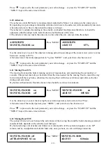
Page 14: ...en made press the MENU key and the new choice has been saved Press to proceed to the next parameter you wish to change or press the START UP and the MENU keys at the same time to finish 6 3 Languages As standard the software includes texts in 5 different languages DANISH DK Press MENU DANISH DK WOODPELLETS PRG 1 ADJUST Select the preferred language with the and keys you may choose between DK S F D...

Page 15: ...hed beyond the set temperature and switches into the pause period fuel must be added in adequate intervals This has 2 purposes to maintain the pilot flame during the pause period and the prevent the embers from creeping backwards through the screw tube If the pause periode is to long you risk that the pilot fire will die or that you are in danger of a backfire On the other hand if you set a too sh...

Page 16: ...selection from 0 to 255sec After selection of the wanted period press MENU and your choice has been saved Press to proceed to the next parameter you wish to change or press the START UP and the MENU keys at the same time to finish 6 9 Manual operation It is possible to manually activate a number of functions and motors this makes it possible to study how they operate MAN operation Press MENU MAN o...

Page 17: ... time to finish 6 11 Moving Floor ON The moving floor and the boiler cleaning system if mounted are activated during the set number of seconds This period must always be shorter than the time needed for the moving floor to run all the way forward and all the way home otherwise the moving floor will run several times right after each other during each activation By boilers with automatic fluetube c...

Page 18: ...to finish 6 14 Transport screw OFF In order to prevent the transport screw from starting and stopping all the time it is possible by means of the OFF period to set the wanted intervals between starts Even if the OFF period has expired the transport screw will not start if influenced by the fuel sensor TRANSPORT SC off Press MENU TRANSPORT SC off SCREW STEP 0 ADJUST 008 MIN Use the arrow keys to se...

Page 19: ...o only under special circumstances the length of the period should be different SCREW STEP 2 Press MENU SCREW STEP 2 SCREW STEP 3 ADJUST 0 80 SEC Use the arrow keys to select the stokerscrew running period select from 0 3 to 52sec After selection of the wanted period press MENU and your choice has been saved Press to proceed to the next parameter you wish to change or press the START UP and the ME...

Page 20: ...10 Use the arrow keys to select the fan speed you may choose between values from 001 to 080 After selection of the wanted fan speed press MENU and your choice has been saved Press to proceed to the next parameter you wish to change or press the START UP and the MENU keys at the same time to finish 6 21 Fan step 2 As a starting point the speed in step 2 should equally be 3 times as high as the valu...

Page 21: ... STEP 0 OXY STEP 1 ADJUST 14 Use the arrow keys to select the oxygen percentage select a value between 5 and 21 After selection of the wanted oxygen press MENU and your choice has been saved Press to proceed to the next parameter you wish to change or press the START UP and the MENU keys at the same time to finish 6 24 Oxygen step 1 The oxygen in step 1 should be set a little lower than in step 0 ...

Page 22: ... 14 the plant will switch into operation and the stoker will start working however should the oxygen fail to to be reduced below 14 before expiration of the STARTUP TIME the plant will stop and the word STOP will appear in the display By some fuel types it may be a little difficult to reduce the oxygen within the set period and therefore it may be an advantage to prolong the STARTUP TIME If the fi...

Page 23: ... keys at the same time to finish 6 30 Startup oxygen limit value The control needs the oxygen value to find out if the fire has gone out This is why we have the parameter OXYGEN LIMIT If the oxygen during step 2 or 3 lies above this limit for a longer period the control will switch into the START UP mode to carefully try to stimulate and quicken the fire If this does not succeed within the above m...

Page 24: ...feeding mode select a value between 001 and up to 255sec After selection of the wanted period press MENU and your choice has been saved Press to proceed to the next parameter you wish to change or press the START UP and the MENU keys at the same time to finish 6 33 Pause screw period When the plant stands still in the pause mode fuel is fed into the plant at adequate intervals The amount of fuel t...

Page 25: ...p to 52sec After selection of the wanted start portion press MENU and your choice has been saved Press to proceed to the next parameter you wish to change or press the START UP and the MENU keys at the same time to finish 6 35 Afterrun Not in use in this standard control AFTERRUN START FUEL 2 3 Therefore Press to proceed to the next parameter you wish to change or press the START UP and the MENU k...

Page 26: ...ed and go lower if the fan is adjusted to lower speed The smokefan have to run in such a speed that you not are getting smoke out in the back screwchannal flamedamper If it runs to fast it will take to much dust out in the Chimney SMOKEFAN Press MENU SMOKEFAN SMOKEFAN START ADJUST 85 Use the arrow keys to select the speed on the smokefan in percentage of the combustion fan select a value between 1...

Page 27: ...o below the limit value before expiration of the start up period and the plant will stop On the other hand if we feed in fuel too early the fire is suffocated before it even started OSP Press MENU OSP SHOW SCREW PAUSE ADJUST 002 MIN Use the arrow keys to select the required laggard select a value between 1 and up to 255min After selection of the wanted laggard press MENU and your choice has been s...

Page 28: ...an running Pour a little ignition liquid grill igniters onto the pellets and set fire Once the pellets have caught fire re start the stoker black button Press STOP SCREW and let it stay inactivated until the combustion is well established then press START SCREW and the screw feedings are from now on decided by the control impulses Always make sure that the circulation pump is switched off when you...

Page 29: ...display P2 to the value 1 and thus have the actual pause time shown in the display Also see item 6 15 in the section Menus and Their Adjustments For you as the enduser the typical final adjustment proceedings would be to write down the values shown in the display during some days and then make adjustments if any regarding the screw running time The below example states a number of data registered ...

Page 30: ... sec Step 2 1 30 sec Step 3 2 60 sec 10 0 Closing Down The Plant When closing down the stoker plant we recommend you to follow the below procedure Set the boiler temperature at 20 C below the actual temperature and the stoker will pause Press the STOP SCREW button so that no more fuel is entered into the plant Wait for 5 10 minutes to allow for all the fuel in the combustion chamber to burn Turn o...

Page 31: ...maximum output and the Undertemp function has been switched off During the first 15 min the control will be locked at the wood program and then the combustion air fan will automatically adapt to requirements The combustion air fan will reach the set temperature WOOD TEMP and then switch to pause As long as the control operates in WOOD TEMP it will stay in pause until the temperature has dropped be...

Page 32: ...change if necessary The bottom nozzles must be placed so that the air is blown across the fuel in an angle of about 45 degrees The holes in the top nozzle just have to point forward in an oblique direction It may be necessary to dismount the nozzles to clean them from ashes KSM recommend that they are cleaned once a year before the start of the new heating season However a more frequent cleaning m...

Page 33: ...ly open the external screw will start running The sensor reports to the control when fuel is registered again The screw stops and the damper close slowly to allow for the damper to be completely empty before it is fully closed Adjustment possibilities see section 6 13 6 14 TRANSPORT SC On Is the maximum time in seconds when damper and screw are activated however the process is stopped earlier if t...

Page 34: ...of the burner head The scraper goes backwards underneath the fuel and stops when it hits the back of the burn head The scraper should always only run once and stop after each operation Adjustment possibilities see section 6 11 6 12 MOVING FLOOR On Is the maximum time in seconds when the scraper controller is activated the period is normally set at 5 seconds MOVING FLOOR Off The time interval for t...

Page 35: ... of a 20 litre ash bin which is filled from the bottom like a molehill Adjustment possibilities see section 6 10 The ash screw runs parallel to the stoker screw use parameter ASH SCREW to set its capacity as a percentage of the stoker screw capacity As a starting point set it at 3 10 later on adjust the setting to the ash volume Maintenance Clinker crust By heavy formation of clinker it may be nec...

Page 36: ...ore fuel for the ignition function Normal value for the OSB is 3 minute STARTUP FAN Determines how strong the fan should run in start up mode STARTUP TIME Should it unlikely failure to get oxygen down by the end of STARTUP TIME the boiler will stop and must be manually restarted AUT IGNITION The automatic ignition is a good solution in combination with solar heating 0 No Automatic Ignition 1 The I...

Page 37: ... whereas ashes from grain are darker and coarser Approximately twice during the heating season you should clean the boiler flue gas ducts this is done through the cleaning door at the boiler top Remove the cover plate on the boiler top the cleaning flap sits right underneath it Unscrew the 4 nuts and remove the flap this will give ample space for brushing down the flue gas ducts Please find below ...

Page 38: ...he stoker if the lid is opened This is to protect you against any damage while handling screw or stirring device 18 3 Electric Protection Fuses The KSM Stoker control is furnished with overload protection on each motor which is triggered if the screw motor should be exposed to overcharge Furthermore fuses are mounted inside the control as a protection of the control itself and its other components...

Page 39: ...sult will be a poor combustion The nozzles shall be remounted with some heat proof gun gum as described in section 12 19 4 Screw Tube As occasion requires clean this tube for clinker once or twice during each heating season in the area where the tube runs into the burner head Be particularly careful to remove any clinker in the corners seeing that this may otherwise prevent the fuel from moving fo...

Page 40: ...clunch the screw by pressing the Start button 2 The motor hums The screw has stuck due to a foreign body or some moist fuel in the screw Dismount the screw and clean the screw tube 20 6 Backfire If you have been very unlucky and the thermal valve has been triggered it is necessary to clear out the screw for moist pellets before re starting the plant The easiest way is to dismount the 4 bolts holdi...

Page 41: ... to corrosion and reduce the life of both boiler and flue gas ducts Moreover it is recommended to raise the boiler temperature as this contributes to avoid the condensing The above mentioned draught stabiliser also adds to ensure a healthy chimney seeing that fresh air will constantly be drawn through the chimney helping to keep it dry Also heating with firewood will easily result in condense wate...

Page 42: ... are manufactured from 2mm sheets if elbows occur on flue gas outlets it is necessary to use elbows with cleaning flap If long free flue gas ducts are applied they should be insulated in order to avoid condensed water which would result in corrosion problems All joints must be tight use furnace cement or glass string to tighten the joints As for the chimney itself it must either be from stainless ...

Page 43: ...he plant is not operating during wintertime it must be drained unless it is otherwise protected against the formation of ice for example by adding a sufficient amount of anti freeze solution to the water 21 2 5 Check the screw direction of rotation Before starting up you must make sure that the screw turns in the correct direction clockwise when observed from behind the stoker If the screw turns i...

Page 44: ...ow at nominal output using wood pellets 123 5 cbm h moisture at TFlue Fluegas volume flow at nominal output using wood pellets 47 0 cbm h moisture at TFlue Required flue draught 10 Pa Power consumption 144 W Power connection 3 x 380 Volt 50 Hz 16 Amp CE plug with 0 and earthing Gearmotor 3x380V 0 37kW 400 rpm I 100 1 Combustion air fan 230V 120W 1750 rpm 420 cbm h Fluegas outlet stud External diam...

Page 45: ... 42 24 0 Piping Diagramme Titel Drawing No 3 Way Mixer valve RD 010 Cooling coil RD 012 Safety valve backfire RD 013 All appertaining drawings appear from the following pages ...

Page 46: ......

Page 47: ......

Page 48: ......

Page 49: ... 43 25 0 Power Diagram Titel Drawing No Internal connections ED 0110 Wiring diagram ED 0148 Terminal list ED 0148 All appertaining drawings appear from the following pages ...

Page 50: ......

Page 51: ......

Page 52: ......

Page 53: ......

Page 54: ...on Auto Zündung 10 40 EL Tænding Auto Ignition Auto Zündung 11 11 41 Lågekontakt silo Tank Cover Switch Deckelschalter behälter 13 42 Lågekontakt silo Tank Cover Switch Deckelschalter behälter 14 12 47 Linax Skrabebund 24VDC Linax Moving floor 24VDC Linax Schubboden 24VDC 6 48 Linax Skrabebund 24VDC Linax Moving floor 24VDC Linax Schubboden 24VDC 7 13 49 Overkog Prime Switch Überhitz Schalter C 50...

Page 55: ...ving floor ON 5 5 5 5 5 5 Moving floor OFF 60 40 20 60 40 20 Transport sc on 90 90 90 90 90 90 Transport sc off 5 5 5 5 5 5 Screw step 0 sek 0 40 1 20 0 80 0 16 0 5 0 33 Screw step 1 sek 0 80 2 40 1 60 0 33 1 00 0 66 Screw step 2 sek 1 60 4 80 3 20 0 66 2 00 1 30 Screw step 3 sek 3 20 9 4 80 1 30 4 00 2 60 Fan step 0 5 5 5 5 5 5 Fan step 1 25 25 25 25 25 25 Fan step 2 50 50 50 50 50 50 Automatic a...

Page 56: ...25 25 25 Oxy limit value 15 15 15 15 15 15 Pause fan 10 10 10 10 10 10 Pause fan time 10 10 10 10 10 10 Pause screw ON 3 2 9 4 8 1 3 4 2 6 Start Portion 3 20 9 4 80 1 30 4 00 2 60 Afterrun 0 0 0 0 0 0 Start fuel 2 3 0 33 0 33 0 33 0 33 0 33 0 33 Boiler temp start 3 3 3 3 3 3 Smoke fan 50 50 50 50 50 50 Smoke fan start 50 50 50 50 50 50 Aut Ignition 0 0 0 0 0 0 Show screw pause 1 1 1 1 1 1 End 0 0 ...

Page 57: ...0 Moving floor ON 5 5 5 5 5 5 Moving floor OFF 60 40 20 60 40 20 Transport sc on 90 90 90 90 90 90 Transport sc off 5 5 5 5 5 5 Screw step 0 sek 1 00 3 00 2 00 0 16 0 50 0 33 Screw step 1 sek 2 00 6 00 4 00 0 33 1 00 0 66 Screw step 2 sek 4 00 12 8 0 66 2 00 1 30 Screw step 3 sek 8 24 16 1 30 4 00 2 60 Fan step 0 5 5 5 5 5 5 Fan step 1 25 25 25 25 25 25 Fan step 2 50 50 50 50 50 50 Automatic and 5...

Page 58: ...tup fan 25 25 25 25 25 25 Oxy limit value 15 15 15 15 15 15 Pause fan 10 10 10 10 10 10 Pause fan time 10 10 10 10 10 10 Pause screw ON 4 12 8 0 66 2 1 3 Start Portion 4 12 8 1 4 3 Afterrun 0 0 0 0 0 0 Start fuel 2 3 0 33 0 33 0 33 0 33 0 33 0 33 Boiler temp start 0 0 0 0 0 0 Smoke fan 50 50 50 50 50 50 Smoke fan start 50 50 50 50 50 50 Aut Ignition 2 2 2 3 3 3 Show screw pause 1 1 1 1 1 1 End 0 0...

Page 59: ... 5 10 Moving floor ON 5 5 5 5 5 5 Moving floor OFF 60 40 20 60 40 20 Transport sc on 90 90 90 90 90 90 Transport sc off 5 5 5 5 5 5 Screw step 0 sek 0 40 1 70 0 80 0 40 1 70 0 80 Screw step 1 sek 0 80 3 50 1 70 0 80 3 50 1 70 Screw step 2 sek 1 70 7 3 50 1 70 7 3 50 Screw step 3 sek 3 50 14 7 3 50 14 7 Fan step 0 5 5 5 5 5 5 Fan step 1 25 25 25 25 25 25 Fan step 2 50 50 50 50 50 50 Without ignitio...

Page 60: ...5 25 25 25 25 Oxy limit value 15 15 15 15 15 15 Pause fan 10 10 10 10 10 10 Pause fan time 10 10 10 10 10 10 Pause screw ON 1 7 7 3 5 1 7 7 3 5 Start Portion 1 70 7 3 50 1 70 7 3 50 Afterrun 0 0 0 0 0 0 Start fuel 2 3 0 33 0 33 0 33 0 33 0 33 0 33 Boiler temp start 3 3 3 3 3 3 Smoke fan 50 50 50 50 50 50 Smoke fan start 50 50 50 50 50 50 Aut Ignition 0 0 0 1 1 1 Show screw pause 1 1 1 1 1 1 End 0 ...

Page 61: ... 44 Supplement C ...

Page 62: ... 45 ...

Page 63: ... 46 ...

Page 64: ... 47 ...

Page 65: ...ltistoker 575 50 Auto M 00575100 KSM Multistoker 575 50 F Auto M 00575200 KSM Multistoker 575 50 FX M 00575300 More dimension drawings can be downloaded at https www dropbox com sh 4q2fp5a2tpjedoy AACTo6xIHdEHbFGURiVXg7l8a Dimension 20drawings PDF dl 0 ...

Page 66: ......

Page 67: ......

Page 68: ......

Reviews: