24
EN
05/2016
8.4 Maintenance of the magnetic switch
8.5 Functional test of the magnetic switch
The units must be installed and commissioned in accordance with the generally accepted rules of engineering
practice. When in service the units do not require any maintenance, provided that the magnetic switch is
designed for the ambient conditions such as the temperature and protection rating.
With the electrical connection between the switch and the control disconnected, a continuity tester is then
connected and the functionality of the switch is tested using a magnet. Bistable switches should be switched
twice so that they are returned to their initial position. Reconnect the electrical connection after the test has
been completed.
8.6 Notes for magnetic switch
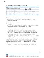
8.7 Nominal data for ex-magnetic switch
• Do not operate magnetic switches near strong electromagnetic fields. ( Minimum distance 1 m )
• The magnetic switch may not be exposed to mechanical load, vibrations and impacts. If these loads
are present, damping elements must be used.
• The switching points for the magnetic float switch must not be blocked.
• If there is a risk that the liquid could ignite or explode, then devices that conform to the
ATEX directive 2014/34/EU must be used.
• The environmental conditions must be such that all display instruments can be read without errors on-site,
and if possible, at a horizontal angle.
• The devices must be disposed of according to regional and national regulations and directives.
When the device is being disposed of, liquid residues may remain in it.
TRANSPORT REGULATIONS:
When packing for transport, be aware that the devices are measurement systems with electronic
components. The devices must be packed accordingly. The outer packing material such as wood, cardboard,
etc. must be marked with hazard warning signs.
ATEX
Type of protection intrinsic safety Ex ia IIC
I
i
≤ 100 mA
Type of protection intrinsic safety Ex ia IIC with option /R22 ( resistor )
I
i
≤ 100 mA
Type of protection intrinsic safety Ex ia IIC with option /N ( NAMUR EN 60947 )
U
i
≤ 15 VDC
I
i
≤ 60 mA
Type of protection “flameproof enclosure”
U
N
≤ 250 VDC/AC
I
N
≤ 100 mA
Type of protection “flameproof enclosure” with option /R22 ( resistor )
U
N
≤ 250 VDC/AC
I
N
≤ 100 mA
P
V
≤ 0.21 W
Type of protection “flameproof enclosure” with option /N ( NAMUR EN 60947 )
U
N
≤ 15 VDC
I
N
≤ 60 mA
Type of protection “INTRINSIC SAFETY”
• The effective self inductance and capacitance are negligible.
• Only for connection to a certified intrinsically safe circuit.
Type of protection “FLAMEPROOF ENCLOSURE”
• Only for connection to a circuit with safe limitation of the electrical parameters of the above values.
• If the instrument will be supplied without cable gland, it is only allowed to mount a cable gland which is
according to norm EN 60079-1 ( pressure die-cast Exd ).
Heinrich Kübler AG
Ruessenstrasse 4 | CH-6340 Baar | T41 (0)41 766 62 62 | Fax +41 (0)41 766 62 63 | E-Mail info@kubler.ch | Internet www.kubler.ch


