32
EN
05/2016
Key 1
…
-
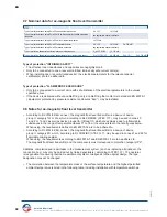
Bypass chamber additional design
Key 2
… /
…
/ … -
Bypass chamber outside diameter
Key 3
… / … /
…
-
Bypass chamber wall thickness
Key 1
…
/ … / … -
Bypass chamber material quality
Stainless steel
Stainless steel electropolished / Ra ca. 0,8μm
( not attestable )
Titanium
Alloy C
6Mo
Steel ( only ACS.. )
Stainless steel ECTFE coated
Stainless steel PFA coated
Stainless steel ETFE coated
PVC
Polypropylene
PVDF
Ø 32.00 mm ( P )
Ø 60.30 mm ( V / VP / TI / CS )
Ø 60.33 mm ( V / VP / MO / HC / CS )
Ø 63.00 mm ( P / PP / PF )
Ø 63.50 mm ( V / VP / VEEC / VPFA / VETF )
Ø 73.03 mm ( V / VP / MO / TI / HC / CS )
Ø 76.10 mm ( V / VP )
Ø 88.90 mm ( V / VP / CS )
Ø 114.30 mm ( V / VP / CS )
Bypass chamber wall thickness in mm
( see the relevant catalog page or
by calculation )
Steam tracing system with outer tube Ø 76.10 x 2.00 mm
Differential compensated
2-chamber system with G / BSP socket ( only for bypass level indicator ACS2 )
2-chamber system with NPT socket ( only for bypass level indicator ACS2 )
HM76
1
DK
1
ZK1
1
ZK2
1
V
1
VP
1
TI
1
HC
1
MO
1
CS
1
VEEC
1
VPFA
1
VETF
1
P
PP
PF
32
60
1
61
1
63
63
1
73
1
76
1
88
1
114
1
…
1
Code 7
Code 8
Key 1
…
-
Centre distance / Length of instrument
Centre distance in mm
Length of instrument in mm ( only for instrument without process side connections )
Code 6
M…
1
L…
1
Key 1
…
-
Electrical connection position of the level transmitter
Electrical connection top mounted
Electrical connection bottom mounted
Code 5
DO
1
DU
1
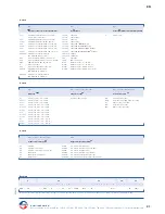
Code
1
2
3
4
5
6
7
8
Key
1
-
1
-
1.1
/
1.2
/
1.3
-
1
/
2
/
3
/
4
/
5
/
6
/
7
/
8
-
1
-
1
-
1
/
2
/
3
-
1
-
Example
BMG - FE -
25
/
16
/
B1
- ALF /
TP43B
/
V
/ K15 /
EXIAG - DU - M… - V
/ 60 /
2
-
-
Example
Black = not possible according to Atex /
Blue = possible according to Atex Exia
/
Blue
1
= possible according to Atex Exia and Exd
/ Black
1
= possible according to Atex Exd
Heinrich Kübler AG
Ruessenstrasse 4 | CH-6340 Baar | T41 (0)41 766 62 62 | Fax +41 (0)41 766 62 63 | E-Mail info@kubler.ch | Internet www.kubler.ch


