25
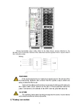
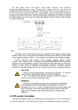
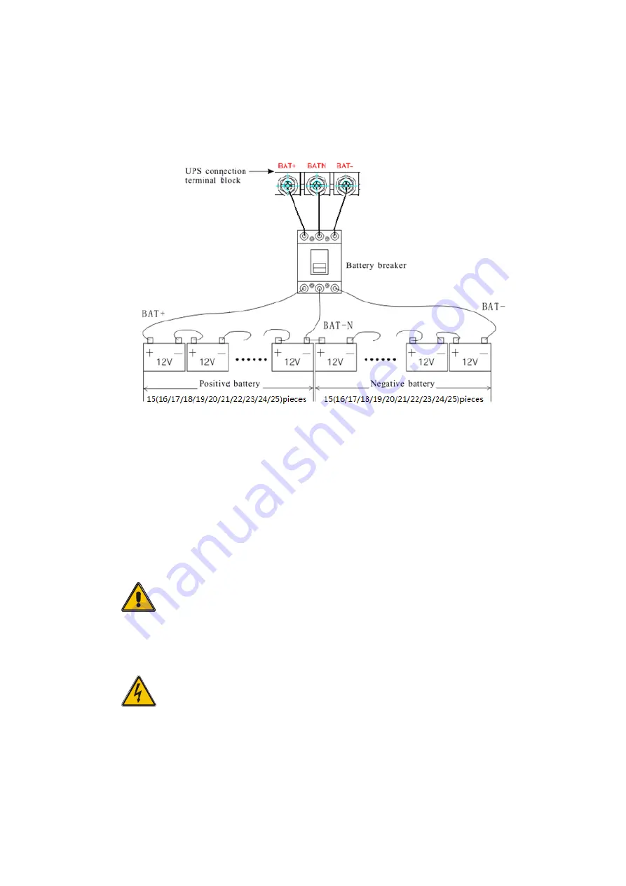
The UPS adopts positive and negative double battery framework, total 30(optional
32/34/36/38/40/42/44/46/48/50) in series. A neutral cable is retrieved from the joint between the
cathode of the 15
th
(16
th
/17
th
/18
th
/19
th
/20
th
/21
th
/22
th
/23
th
/24
th
/25
th
) and the anode of the 16
th
(17
th
/18
th
/19
th
/20
th
/21
th
/22
th
/23
th
/24
th
/25
th
/26
th
) of the batteries. Then the neutral cable, the battery
Positive and the battery negative are connected with the UPS respectively. The battery sets between
the Battery anode and the neutral are called positive batteries and that between neutral and cathode
are called negative ones. The user can choose the capacity and the numbers of the batteries
according to their desire.
Note
:
The BAT+ of the UPS connect poles is connected to the anode of the positive
battery, the BAT-N is connected to the cathode of the positive battery and the anode
of the negative battery, the BAT- is connected to the cathode of the negative battery.
Factory setting of the long-run unit is battery quantity---36pcs, battery
capacity---12V 100AH. When connecting 30/32/34/36/38/42/44/46/48/50 batteries,
please re-set desired battery quantity and its capacity after UPS starts at AC mode.
Charger current could be adjusted automatically according to battery capacity
selected. All related settings can be done through LCD panel or monitoring software.
CAUTION!
Ensure correct polarity battery string series connection. i.e. inter-tier
and inter block connections are from (+) to (-) terminals.
Don’t mix batteries with different capacity or different brands, or
even mix up new and old batteries, either.
WARNING!
Ensure correct polarity of string end connections to the Battery
Circuit Breaker and from the Battery Circuit Breaker to the UPS
terminals i.e. (+) to (+) / (-) to (-) but disconnect one or more battery cell
links in each tier. Do not reconnect these links and do not close the
battery circuit breaker unless authorized by the commissioning
engineer.
3.8
UPS parallel Installation
The basic installation procedure of a parallel system comprising of two or more UPS is the same
as that of single system. The following sections introduce the installation procedures specified to
Summary of Contents for HIP3300E
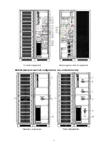
Page 14: ...13 Side View Rear View Full configuration...
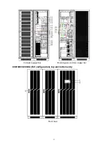
Page 15: ...14 Connect coppper bar Mains bypass common copper bar...
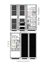
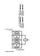
Page 29: ...28 3 9 3 UPS installation The whole systems are showed below 4 Operation 4 1 Operation Modes...
Page 40: ...39...
Page 41: ...40 4 3 3 Alarm View the alarm and history of the UPS and open or close the buzer...
Page 49: ...48...
Page 59: ...58 4 3 5 1 USB Wizard History Output download history and setting record by USB...
Page 60: ...59 4 3 5 1 1 Alarm Log Output 4 3 5 1 2 Setting Log Output...

