6
USER MANUAL
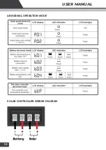
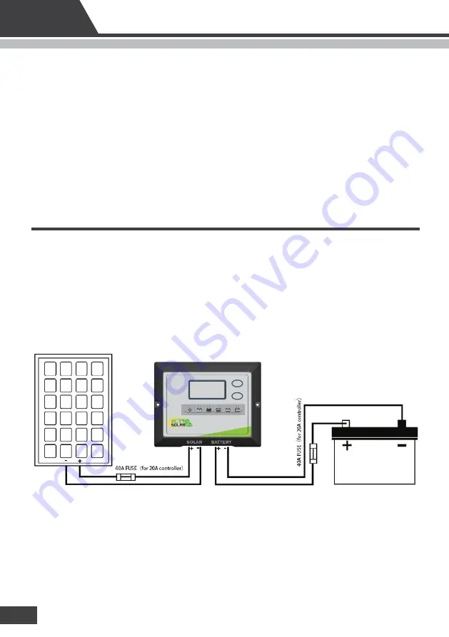
Wiring Connections
To protect the Battery and the Solar Panel, we strongly recommend that you place inline fuse on the
positive wire on both the “Solar” and “Battery” Circuits. 20A fuse for 10A controller, 30A fuse for 15A
controller, 40A fuse for 20A controller, (As close to the Battery / Panel as possible).
The Solar Controller has 4 terminals which are clearly marked ‘Solar’ and ‘Battery’. There is a (12V / 24V)
and earth (GND) terminal for each circuit.
Refer to the wiring diagram below.
• Can be connected to the battery permanently to keep the battery fully charged by using a process
called "floating". This means the controller will stop charging when the battery is full and will
automatically start charging the battery as required. This process will also reduce water loss and help
prevent the battery from 'drying out'.
• Protects your battery from discharge at night. Under low light or no light conditions the solar panel
voltage could be less than the battery voltage. The unit contains a special circuit which prevents
current flowing back from the battery and into the solar panel.
• Coloured LED's to easily indicate the operational status and battery conditions.
• Digital LCD to directly display battery voltage, charging current, charging capacity (Amp hour),
battery types, full charge and faulty codes.
• Multi-charging protections against reverse polarity, short circuit, over temperature, over voltage, etc.
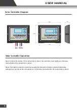
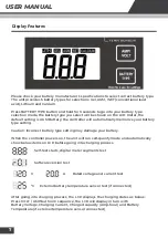
20A 12V
PWM
SOLAR CHARGE CONTROLLER
KT70757
AMP /
VOLT
BATTERY
TYPE
Hold for 3 seconds
for settings
LCD
Summary of Contents for KT70743
Page 11: ...6 10 USER MANUAL ABNORMAL OPERATION MODE SOLAR CONTROLLER WIRING DIAGRAM...
Page 14: ...13 USER MANUAL...
Page 15: ...8 14 USER MANUAL...
Page 16: ...15 USER MANUAL...

