background image

-53-

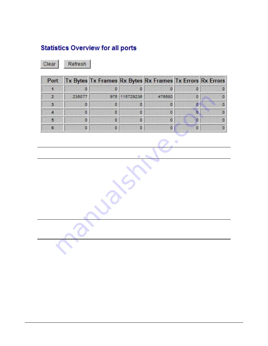
4.14 Statistics Overview

Statistics

Description

Port

Port number

Tx Bytes

Total of bytes transmitted on the port

Tx Frames

Total of packet frames transmitted on the port

Rx Bytes

Total of bytes received on the port

Rx Frames

Total of packet frames received on the port

Tx Errors

Total of error packet frames transmitted on the port

Rx Errors

Total of error packet frames received on the port

[Clear]

Click to reset all statistic counters

[Refresh]

Click to refresh all statistic counters

Summary of Contents for KGS-510F-B

Page 1: ... 1 KGS 612F Web Smart 6 Port Gigabit Ethernet Switch with Fiber Connectivity User s Manual DOC 111205 ...

Page 2: ...erves the right to revise this documentation and to make changes in content from time to time without obligation on the part of KTI Networks Inc to provide notification of such revision or change For more information contact United States KTI Networks Inc P O BOX 631008 Houston Texas 77263 1008 Phone 713 2663891 Fax 713 2663893 E mail kti ktinet com URL http www ktinet com International Fax 886 2 ...

Page 3: ...nterface cables and AC power cord if any must be used in order to comply with the emission limits CISPR A COMPLIANCE This device complies with EMC directive of the European Community and meets or exceeds the following technical standard EN 55022 Limits and Methods of Measurement of Radio Interference Characteristics of Information Technology Equipment This device complies with CISPR Class A WARNIN...

Page 4: ...ns 16 3 1Abbreviation 16 3 2 QoS Function 17 3 2 1 Packet Priority Classification 18 3 2 2 Priority Class Queues 18 3 2 3 Egress Service Policy 18 3 3 VLAN Function 19 3 3 1 VLAN Operation 19 3 3 2 Ingress Rules 19 3 3 2 1 802 1Q Tag Aware Per port setting 19 3 3 2 2 Keep Tag Per port setting 19 3 3 2 3 Drop Untag Per Port Setting 20 3 3 2 4 Drop Tag Per Port Setting 20 3 3 3 Ingress Default Tag P...

Page 5: ...ettings 37 4 6 3 4 VLANGroups 39 4 6 4 Important Notes for VLAN Configuration 40 4 7Aggregation 41 4 8 LACP 42 4 9 RSTP 43 4 10 802 1X Configuration 44 4 10 1 802 1X Re authentication Parameters 46 4 11 Mirroring 47 4 12 Quality of Service 48 4 12 1 802 1p Mapping 49 4 12 2 DSCP Mapping 50 4 12 3 QoS Service Policy 51 4 13 Storm Control 52 4 14 Statistics Overview 53 4 15 Detailed Statistics 54 4 ...

Page 6: ... mini GBIC SFP port can also be installed with an optional SFP optical fiber transceiver to support one Gigabit fiber connection when needed Web Management The switch is embedded with an Http server which provides management functions for advanced network functions including Port Control Quality of Service and Virtual LAN functions The manage ment can be performed via Web browser based interface o...

Page 7: ...control function z Supports port based and 802 1Q Tag based VLAN z Provides QoS function z Provides link aggregation port trunking function with LACP support z Provides port mirroring function z Provides 802 1X authentication for port access z Supports 802 1w RSTP 802 1D STP and 802 1S MSTP z Watchdog timer function z Supports SFPwithDigitalDiagnostic Monitoring DDM z Provides packet storm control...

Page 8: ...000Mbps Duplex support Full Half duplex Network cable Cat 5 UTP Combo Port with 10 100 1000 RJ 45 and 1000Mbps Mini GBIC SFP Copper interface Compliance IEEE 802 3 10Base T IEEE 802 3u 100Base TX IEEE 802 3u 1000Base T Connectors Shielded RJ 45 jacks Pin assignments Auto MDI MDI X detection Configuration Auto negotiation or software control Transmission rate 10Mbps 100Mbps 1000Mbps Duplex support ...

Page 9: ...5 Eye safety IEC 825 compliant Switch Functions MAC Addresses Table 8K entries Forwarding filtering Non blocking full wire speed Switching technology Store and forward Maximum packet length 1526 bytes Jumbo frame support disabled Flow control IEEE 802 3x pause frame base for full duplex operation Back pressure for half duplex operation VLAN function Port based VLAN and IEEE 802 1Q Tag based VLAN Q...

Page 10: ...m protection control settings Port statistic LACP status RSTP status Reboot restore factory default update firmware DC Power Input Interfaces DC Jack D 6 3mm D 2 0mm Operating Input Voltages 7 5VDC 5 Power consumption 9W max 7 5V Mechanical Dimension base 180 x 114 x 26 mm Housing Enclosed metal with no fan Mounting Desktop mounting wall mounting Din rail mounting Environmental Operating Temperatu...

Page 11: ...The power cable extension cable or plug is damaged An object has fallen into the product The product has been exposed to water The product has been dropped or damaged The product does not operate correctly when you follow the operating instructions Do not push any objects into the openings of your system Doing so can cause fire or electric shock by shorting out interior components Operate the prod...

Page 12: ...ge matching the commercial power voltage in your area The AC Power Adapter Specifications AC input power AC power voltage of your area options Rated AC120V 60Hz DC7 5V 1 2A Rated AC230V 50Hz DC7 5V 1 2A Rated AC240V 50Hz DC7 5V 1 2A The steps to apply the power to the product are 1 Connect power adapter DC plug to the DC input jack located on the back of the unit before connecting to the AC outlet...

Page 13: ...uto detect the twisted pair signals and adapts itself to form a valid MDI to MDI X connection with the remote connected device automatically No matter a straight through cable or crossover cable is connected the ports can sense the receiving pair automatically and configure itself to match the rule for MDI to MDI X connection It simplifies the cable installation Auto negotiation Function The ports...

Page 14: ...er is seated securely in the slot place the bail in lock position Connecting Fiber Cables LC connectors are commonly equipped on most SFP transceiver modules Identify TX and RX connector before making cable connection The following figure illustrates a connection example between two fiber ports Make sure the Rx to Tx connection rule is followed on the both ends of the fiber cable Network Cables Mu...

Page 15: ...n 2 10 Configuring IP Address and Password for the Switch The switch is shipped with the following factory default settings for software management Default IP address of the switch 192 168 0 2 255 255 255 0 The IP Address is an identification of the switch in a TCP IP network Each switch should be desig nated a new and unique IP address in the network Refer to Web management interface for System C...

Page 16: ...rd Ethernet frame with no VLAN Tag field Priority tagged packet An IEEE 802 1Q packet which VID filed value is zero VID 0 VLAN Tagged packet An IEEE 802 1Q packet which VID filed value is not zero VID 0 PVID Port VID PVID is the default VID of an ingress port It is often used in VLAN classification for untagged packets It is also often used for egress tagging operation DSCP Differentiated Service ...

Page 17: ...on to guide the packet forwarding in four priority classes The versatile classification methods can meet most of the application needs The following figure illustrates the QoS operation flow when a packet received on the ingress port until it is transmitted out from the egress port ...

Page 18: ... to an egress port 3 2 2 Priority Class Queues Each egress port in the switch is equipped with four priority class egress queues to store the packets for transmission A packet is stored into the class queue which is associated to the classified priority class For example a packet is stored into Class 3 egress queue if it is classified as priority Class 3 3 2 3 Egress Service Policy Each port can b...

Page 19: ...ring and packet tag removal The related Ingress port settings are 3 3 2 1 802 1Q Tag Aware Per port setting Tag aware 802 1Q Tag Aware mode is used The switch examines the tag content of every received packets For a VLAN tagged packet the packet VLAN tag data is retrieved as packet tag information for VLAN classification and egress tagging operation For untagged packet and priority tagged packet p...

Page 20: ...en Ingress port default tag is used it is copied as packet associated Packet Tag Information for VLAN classification The PVID is used as index to one VLAN group in VLAN group table 3 3 4 Packet Tag Information Under VLAN process every packet is associated with one Packet Tag information in packet forward ing operation The tag information includes VID CFI and User Priority data and is used for two ...

Page 21: ...ropped Refer to section 3 2 4 for details about how the Packet Tag information is generated The member ports specified in the matched VLAN group are the admitted egress port range for the packet The packet will never be forwarded to other ports which are not in the member ports The Source Port Check setting of the matched VLAN group is also referred If it is enabled the ingress port will be checke...

Page 22: ...roups VLAN Group Settings per group VID Member Ports Source Port Check Egress Settings Insert Tag Untagging Specific VID Untagged VID VLAN range supported 1 4095 eight VLANs at the same time PVID VID Untagged VID value range 1 4095 3 4 802 1X Authentication For some IEEE 802 LAN environments it is desirable to restrict access to the services offered by the LAN to those users and devices that are p...

Page 23: ...cation of the supplicant At this point in the process the port on the switch is connected from a physical standpoint however the 802 1X process has not authorized the port and no frames are passed from the port on the supplicant into the switching engine If the PC attached to the switch did not understand the EAP PDU that it was receiving from the switch it would not be able to send an IDand the p...

Page 24: ...nd enter the IP address of the switch unit to which you want to connect The IP address is used as URL for the browser software to search the device URL http xxx xxx xxx xxx Factory default IP address 192 168 0 2 4 2 Login to the Switch Unit When browser software connects to the switch unit successfully a Login screen is provided for you to login to the device as follows The switch will accept only...

Page 25: ...ring Port mirroring related configuration QoS Quality of Service related configuration Storm Control Packet Storm protection control configuration Monitoring Statistics Overview List simple statistics for all ports Detailed Statistics List detailed statistics for all ports LACP Status LACP port status RSTP Status RSTP protocol status Ping Ping command from the switch to other IP devices Maintenanc...

Page 26: ... 26 4 4 System ...

Page 27: ...ion VID VLAN ID configured for web management to the switch CFI CFI value for web reply packets from the switch User priority Priority value for web reply packets from the switch Name Set the system name for this switch unit Password Set new password SNMP enabled Enable SNMP agent SNMPTrap destination The IP address of the SNMP trap manager SNMP Read community The community allowed for the SNMP ge...

Page 28: ...gs is not zero The switch web http server only accepts tagged management packets matched Management VLAN VID and replies tagged packets with tag composed of Management VLAN VID CFI and User Priority settings to the manage ment host The egress port will also be limited in the member ports of the matched VLAN group Summary of the rules VLAN Function Management VID Switch Embedded Web Server operatio...

Page 29: ... 10 Full Disable 10M Full 100 Half Disable 100M Half 100 Full Disable 100M Full 1000 Full Enable 1000M Full Force 1000 Full Disable 1000M Full Flow Control Set port flow control function v set to enable 802 3x pause flow control for ingress and egress SFP DDM Click to display DDM information and status of the SFP transceivers Apply Click to apply the configuration change Notes 1 For 100M fiber app...

Page 30: ...nce SONET compliance information of the transceiver GbE Compliance Gigabit Ethernet compliance information of the transceiver Vendor Name The vendor name of the transceiver Vendor OUI The vendor OUI of the transceiver Temperature The current temperature sensed inside the transceiver Voltage The working voltage sensed inside the transceiver TX Power The transmission optical power sensed Refresh Cli...

Page 31: ...freely with no VLAN limitation Port based VLAN Mode Simple configuration for 2 port based VLAN groups Port based VLAN ISP Mode Simple configuration for 5 port based VLAN groups Advance VLAN Mode Full VLAN configuration for port based and Tag based VLAN Apply Click to apply the configuration change Refresh Click to refresh current configuration ...

Page 32: ... change Refresh Click to refresh current configuration Back Click to go back to upper menu Operation in this mode 1 The member ports of two groups are allowed to overlap 2 The member ports in same group can communicate with other members only 3 No packet tag is examined 4 A received packet will not be modified i e tagging or untagging through VLAN operation till it is transmitted ...

Page 33: ...ased VLAN groups are configured as follows auto matically Group 1 member Port 1 Port 6 Group 2 member Port 2 Port 6 Group 3 member Port 3 Port 6 Group 4 member Port 4 Port 6 Group 5 member Port 5 Port 6 Mode Operation 1 The joint port is the shared member port for all groups 2 Two member ports are configured in each group 3 The member ports in same group can communicate with other only 4 No packet...

Page 34: ...tion Ingress Default Tag Click to configure per port Ingress Default Tag settings Ingress Settings Click to configure per port ingress settings Egress Settings Click to configure per port egress settings VLAN Groups Click to configure VLAN group table ...

Page 35: ...ID is used as index for VLAN classification VLAN group table lookup in one of the following conditions 1 Ingress port Tag Aware setting Tag ignore 2 Ingress port Tag Aware setting Tag aware and the received packet is untagged or priority tagged PVID CFI User Priority Ingress Default Tag for the ingress port It is used as the tag for insertion in egress tagging operation in one of the following con...

Page 36: ...xists Enable set to activate tag removal for VLAN tagged packets Disable set to disable tag removal function Drop Untag Drop all untagged packets and priority tagged packets Enable drop untagged packets and priority tagged packets Disable admit untagged packets and priority tagged packets Drop Tag Drop all VLAN tagged packets Enable drop VLAN tagged packets Disable admit VLAN tagged packets Apply ...

Page 37: ... VLAN classification VLAN table lookup The following table lists the index used Ingress Tag Aware setting Received packet type Tag ignore Tag aware Untagged PVID PVID Priority tagged VID 0 PVID PVID VLAN tagged VID 0 PVID Packet tag VID 3 Both Drop Untag and Drop Tag are set to Disable to admit all packets 4 6 3 3 Egress Settings ...

Page 38: ...his function Untagged VID VID for Untagging Specific VID setting 1 4095 decimal 12 bit VID value Apply Click to apply the configuration change Refresh Click to refresh current configuration Back Click to go back to upper menu The inserted tag sources when Insert Tag Enable are listed as follows Received packet type Tag Aware Tag ignore Tag Aware Tag aware Untagged Ingress Default Tag Ingress Defau...

Page 39: ...for the packets belong to the VLAN Port 1 6 click to select Source Port Check Check whether the ingress port is the member port of the VLAN Enable set to enable this check the packet is dropped if ingress port is not member port of the VLAN Disable set to disable this check Apply Click to apply the configuration change Refresh Click to refresh current configuration Back Click to go back to upper m...

Page 40: ... group are configured with same VLAN configuration and are in same VLAN group 3 Double Tagged in Advanced VLAN Mode For a received packet Ingress port Keep Tag setting and Egress port Insert Tag setting are enabled at the same time It will cause the packet double tagged when egress Although it is often applied in Q in Q provider bridging application However such condition should be avoided in norm...

Page 41: ...wo switches using more than one physical links It can increase the connection bandwidth between two switches The switch supports up to four trunk groups and the number of member ports belonging to one trunk group is not limited Notes 1 The LACP enabled ports are not available in this configuration 2 One port cannot belong to two trunk groups at the same time 3 The member ports of one trunk group m...

Page 42: ...in same LACP link aggregate Value 1 255 Auto key value is assigned by the system Apply Click to apply the configuration change Refresh Click to refresh current configuration Notes 1 This configuration is used to configure LACP aggregate groups 2 The ports with same key value are in same LACP aggregate group 3 The ports with Auto key are in same LACP aggregate group 4 The ports configured in non LA...

Page 43: ...w long a bridge should send this message to other bridge to tell I am alive Max Age When the switch is the root bridge the whole LAN will apply this setting as their maximum age time Forward Delay This figure is set by Root Bridge only The forward delay time is defined as the time spent from Listening state moved to Learning state and also from Learning state moved to Forwarding state of a port in...

Page 44: ... listening and learning state because the edge ports cannot create bridging loops in the network Port Path Cost Specifies the path cost of the port that switch uses to determine which port are the forwarding ports the lowest number is forwarding ports the rage is 1 200 000 000 and Auto Auto means a default cost is automatically calculated in RSTP operation based on the port link speed The default ...

Page 45: ...the port is forced to be in authorized state Force Unauthorized the port is forced to be in unauthorized state Port State Port 802 1X state 802 1X Disabled the port is in 802 1X disabled state Link Down the port is in link down state Authorized green color the port is in 802 1X authorized state Unauthorized red color the port is in 802 1X unauthorized state Re authenticate Click to perform a manua...

Page 46: ...ll ports Reauthentication Period The period of time after which the connected radius clients must be re authenticated unit second Value 1 3600 EAPtimeout The period of time the switch waits for a supplicant response to an EAP request unit second Value 1 255 Apply Click to apply the configuration change Refresh Click to refresh current configuration ...

Page 47: ...ort The port is forwarded all packets received on the mirrored ports Mirror Source Select the ports which will be mirrored all received packets to the mirror port Apply Click to apply the configuration change Refresh Click to refresh current configuration ...

Page 48: ...ns are disabled It is also used as default priority class for the received packet when both 802 1p and DSCP classifi cation failed in classification Class 3 Class 0 priority class 802 1p Mapping Click to configure 802 1p mapping tables DSCP Mapping Click to configure DSCP mapping table Service Policy Click to configure per port egress service policy mode Apply Click to apply the configuration chan...

Page 49: ...ty class Mapped priority class for tag m on Port n Class 3 Class 0 Apply Click to apply the configuration change Refresh Click to refresh current configuration Back Click to go back to upper menu Every ingress port has its own 802 1p mapping table The table is referred in 802 1p priority classifica tion for the received packet ...

Page 50: ... user defined DSCP value Class 3 Class 0 All others The other DSCP values not in the seven user defined values are assigned a default priority class Class 3 Class 0 Apply Click to apply the configuration change Refresh Click to refresh current configuration Back Click to go back to upper menu Only one DSCP mapping table is configured and applied to all ports The table is referred in DSCP priority ...

Page 51: ...o 5 3 1 1 Weighted ratio priority Class 3 2 1 0 1 1 1 1 weighted ratio 1 1 1 1 Apply Click to apply the configuration change Refresh Click to refresh current configuration Back Click to go back to upper menu Notes 1 Queue with higher class number has higher priority than queue with lower class number That means Class 3 Class 2 Class 1 Class 0 by default 2 In weighted ratio policies a weighted fair...

Page 52: ...a port Flooded Unicast Rate The rate limit of the flooded unicast packets transmitted on a port The flooded unicast packets are those unicast packets whose destination address is not learned in the MAC address table Apply Click to apply the configuration change Refresh Click to refresh current configuration Notes 1 The unit of the rates is pps packets per second 2 No Limit no protection control ...

Page 53: ...frames transmitted on the port Rx Bytes Total of bytes received on the port Rx Frames Total of packet frames received on the port Tx Errors Total of error packet frames transmitted on the port Rx Errors Total of error packet frames received on the port Clear Click to reset all statistic counters Refresh Click to refresh all statistic counters ...

Page 54: ...54 4 15 Detailed Statistics Button Description Port Click to display the detailed statistics of Port Clear Click to reset all statistic counters Refresh Click to refresh the displayed statistic counters ...

Page 55: ...artner Learning the port is learning by RSTP Forwarding the port is link up and forwarding frames Forwarding the port is link up and forwarding frames and the is the port number of LACP link partner Partner MAC address The MAC address of the link partner at the other end of the LACP aggregate Local Port Aggregated The ports at local end which are aggregated in same LACP group Refresh Click to refr...

Page 56: ...mber Protocol Active yes the port is link up and in LACP operation no the port is link down or not in LACP operation Partner Port Number The port number of the remote link partner Operation Port Key The operation key generated by the system ...

Page 57: ...mal BPDU from designated ports among bridges It decides how long a bridge should send this message to other bridge to tell I am alive 1 10 seconds Max Age When the switch is root bridge the whole LAN uses this setting as the maximum age time 6 40 seconds Fwd Delay This figure is set at Root Bridge only Topology Steady The STP topology is steady Changing The STP topology is changing Root Id The MAC...

Page 58: ...y transition to the forwarding state BPDU data is still received in blocking state Listening The switch processes BPDUs and awaits possible new information that would cause it to return to the blocking state Learning While the port does not yet forward frames packets it does learn source addresses from frames received and adds them to the filtering database switching database Non STP RSTP is disab...

Page 59: ... ping commands generated Time Out in secs The time out for a reply in seconds Apply Start the ping command Status The command status Received replies The number of replies received by the system Request time outs The number of requests time out Average Response Time The average reponse time of a ping request in mini seconds ...

Page 60: ... and Management VLAN configuration 4 21 Update Firmware This menu is used to perform in band firmware switch software upgrade Enter the path and file name of new firmware image file for uploading Configuration Description Filename Path and filename warp format Browse Click to browse your computer file system for the firmware image file Upload Click to start upload 4 22 Logout This menu is used to ...

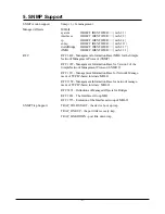
Page 61: ...rotocol SNMP RFC 1907 Management Information Base for Version 2 of the Simple Network Management Protocol SNMPv2 RFC 1213 Management Information Base for Network Manage ment of TCP IP based internets MIB II RFC 1158 Management Information Base for network manage ment of TCP IP based internets MIB II RFC 1493 Definitions of Managed Objects for Bridges RFC 2863 The Interfaces Group MIB RFC 1573 Evol...

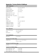
Page 62: ...d SNMPTrap destination 0 0 0 0 SNMP Read community public SNMPWrite community private SNMPTrap community public Ports Configuration Enable Jumbo Frames Not select disabled Mode Auto for all ports Flow Control v Enable VLAN Configuration Main Mode VLAN Disable Port based VLAN Mode setting Member Ports Port 1 2 3 4 5 6 for Group 1 None for Group 2 Port based VLAN ISP Mode setting Joint Port Port 6 A...

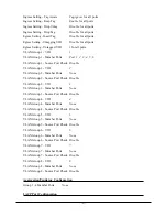
Page 63: ...ember Ports None VLAN Group 2 Source Port Check Disable VLAN Group 3 VID 3 VLAN Group 3 Member Ports None VLAN Group 3 Source Port Check Disable VLAN Group 4 VID 4 VLAN Group 4 Member Ports None VLAN Group 4 Source Port Check Disable VLAN Group 5 VID 5 VLAN Group 5 Member Ports None VLAN Group 5 Source Port Check Disable VLAN Group 6 VID 6 VLAN Group 6 Member Ports None VLAN Group 6 Source Port Ch...

Page 64: ...Delay 15 Force Version Normal 802 1X Configuration Mode Disabled RADIUS IP 0 0 0 0 RADIUS UDP Port 1812 RADIUS Secret None Admin State Force Authorized for all ports Reauthentication Enabled No Reauthentication Period 3600 EAPTimeout 30 Port 1 Port 6 tag 1 Class 0 Port 1 Port 6 tag 2 Class 1 Port 1 Port 6 tag 3 Class 1 Port 1 Port 6 tag 4 Class 2 Port 1 Port 6 tag 5 Class 2 Port 1 Port 6 tag 6 Cla...

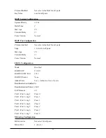
Page 65: ...1 Port 6 tag 6 Class 3 Port 1 Port 6 tag 7 Class 3 QoS DSCP Mapping DSCP 1 Priority 0 Class 0 DSCP 2 Priority 0 Class 0 DSCP 3 Priority 0 Class 0 DSCP 4 Priority 0 Class 0 DSCP 5 Priority 0 Class 0 DSCP 6 Priority 0 Class 0 DSCP 7 Priority 0 Class 0 All others DSCP Class 0 QoS Service Policy Port 1 Strict priority Port 2 Strict priority Port 3 Strict priority Port 4 Strict priority Port 5 Strict p...

Page 66: ...ll others DSCP Class 0 QoS Service Policy Port 1 Strict priority Port 2 Strict priority Port 3 Strict priority Port 4 Strict priority Port 5 Strict priority Port 6 Strict priority Storm Control Configuration Broadcast Rate No limit Multicast Rate No limit Flooded Unicast Rate No limit ...

Reviews: