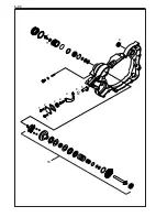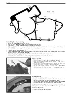
Assembling the engine housing
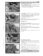
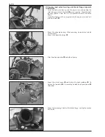
– Remove the engine holder at the mounting rack.
– Make sure that both dowels are properly located in the right housing half.
– Slightly grease the sealing surface of the housing and mount a new gasket.
– Make sure that the rubber is properly inserted into the left housing half and that the sleeves have not slipped off the driving pins
of the shift forks.
– Grease the shaft seal rings of the left housing half and put on the left housing half.
– Check the housing gasket for proper fit.
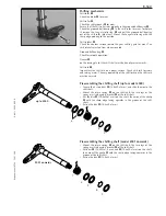
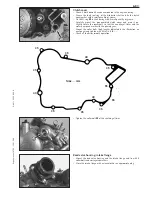
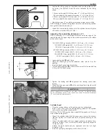
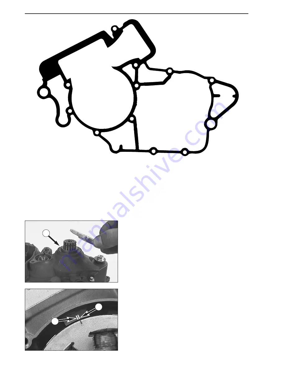
– Grease the threaded sections and the contact surfaces at the heads of the housing bolts. Insert the bolts and assemble the hou-
sing (bolt lengths are indicated in the illustration).
– Before and after tightening the housing bolts with 8 Nm (6 ft.lb.) check all shafts for easy operation.
– Fix the engine on the mounting rack.
– Cut the protruding gasket off cleanly at the sealing surfaces at cylinder base and reed valve housing.
6-3C
M6x... mm
50
50
50
50
50
55
55
50
55
55
55
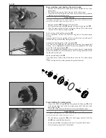
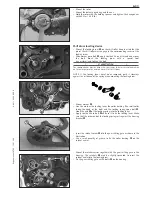
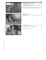
Engine sprocket
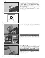
– Oil the O-ring (
≠
1.78 mm) and put it on the countershaft.
– Mount the distance bushing
1
in such a way that the O-ring is
located in the chamfer.
– Put the chain sprocket onto the countershaft with the collar facing
inwards and fix it with the circlip (sharp edge outwards).
– Tap the chain sprocket with a hollow mandrel or a similar tool to
slightly pretension the O-ring and to press the circlip into the groove.
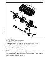
Ignition system
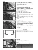
– Insert the woodruff key into the crankshaft.
– Apply Loctite 243 to the thread of the bolt and fix the stator in the
housing with the 3 bolts without yet tightening the bolts.
– Turn the stator so that mark of the stator coincides with the middle
mark of the housing. Then tighten all three bolts of the stator.
NOTE: The left-hand mark
A
in the housing is intended for the 2K-1 and
2K-2 ignition systems. The right-hand mark
B
in the housing is meant for
the 2K-3 ignition system.
– Insert the cable guide into the housing.
1
A
B
Summary of Contents for 125
Page 2: ......
Page 3: ...REPAIR MANUAL ENGINE 125 200 ...
Page 4: ......
Page 6: ......
Page 8: ......
Page 10: ......
Page 12: ......
Page 14: ......
Page 16: ......
Page 22: ......
Page 24: ......
Page 28: ......
Page 30: ......
Page 40: ......
Page 48: ...5 9C 1 1 10 2 3 4 5 6 7 11 8 9 ...
Page 60: ......
Page 72: ......
Page 76: ...7 4C S P O R T M O T O R C Y C L E S 1 2 3 4 5 ...
Page 78: ...7 6C S P O R T M O T O R C Y C L E S 6 9 10 11 ...
Page 80: ...7 8C 1 2 3 4 5 6 ...
Page 86: ......
Page 88: ......
Page 92: ......
Page 128: ......
Page 130: ......
Page 140: ......
Page 141: ...Repair manual KTM 125 200 Art No 3 206 005 E 11 2C ...
Page 142: ...11 3C ...
Page 143: ...Repair manual KTM 125 200 Art No 3 206 005 E 11 4C ...
Page 144: ...11 5C ...
Page 145: ...Repair manual KTM 125 200 Art No 3 206 005 E 11 6C ...
Page 146: ......
Page 147: ...Repair manual KTM 125 200 Art No 3 206 005 E 11 8C S P O R T M O T O R C Y C L E S ...
Page 148: ...11 9C S P O R T M O T O R C Y C L E S ...
Page 149: ...Repair manual KTM 125 200 Art No 3 206 005 E 11 10C ...
Page 152: ...11 13C 125 200 EXC 2001 2002 ...
Page 154: ......
Page 155: ...11 15C Repair manual KTM 125 200 Art No 3 206 005 E KTM 125 200 EXC 2001 2002 ...
Page 156: ...11 16C 125 200 EXC 2003 ...
Page 157: ...11 17C Repair manual KTM 125 200 Art No 3 206 005 E KTM 125 200 EXC 2003 ...
Page 158: ...11 18C 125 200 EXC 2003 ...
Page 159: ...Click below to find more Mipaper at www lcis com tw Mipaper at www lcis com tw ...

