31/CARBURETOR
152
21.13
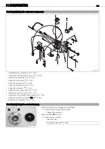
Checking the throttle valve sensor
TPS
Info
The value in the figure is an example only!
–
Remove the carburetor. (
–
Check the throttle slide. (
700063-10
Condition
Component temperature: 20
°C (68
°F)
–
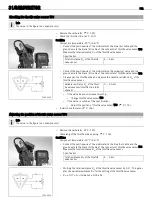
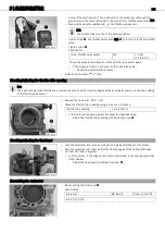
Connect the positive wire of the multimeter to the blue (bu) cable and the
ground wire to the black
(bl) cable of the connector of throttle valve sensor
TPS
.
Measure the total resistance
R
tot
of the throttle valve sensor.
Specification
Total resistance
R
tot
of the throttle
valve sensor
4… 6
k
Ω
700064-10
–
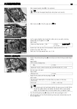
Connect the positive wire of the multimeter to the yellow
(ye) cable and the
ground wire to the black
(bl) cable of the connector of throttle valve sensor
TPS
.
–
Slowly open the throttle slide and measure the variable resistance
R
var
of the
throttle valve sensor.
Variable resistance
R
var
of the throt-
tle valve sensor (throttle slide fully
opened)
3… 4.5
k
Ω
» If the value does not increase smoothly:
–
Change throttle valve sensor
TPS
.
» If the value is outside of the specification:
–
Adjust the position of throttle valve sensor
TPS
–
Install the carburetor. (
21.14
Adjusting the position of throttle valve sensor
TPS
Info
The value in the figure is an example only!
–
Remove the carburetor. (
–
Check/adjust the throttle slide opening. (
700063-10
Conditions
Component temperature: 20
°C (68
°F)
–
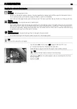
Connect the positive wire of the multimeter to the blue
(bu) cable and the
ground wire to the black
(bl) cable of the connector of throttle valve sensor
TPS
.
Measure the total resistance
R
tot
of the throttle valve sensor.
Specification
Total resistance
R
tot
of the throttle
valve sensor
4… 6
k
Ω
700064-10
–
Multiply the total resistance
R
tot
of the throttle valve sensor by 0.17. This gener-
ates the variable resistance
R
var
for the setting of the throttle valve sensor.
–
R
tot
x 0.17 = R
var
(tolerance
±
0.05
k
Ω
)

