31/CARBURETOR
153
700066-10
–
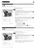
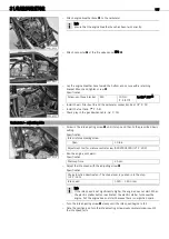
Connect the positive wire of the multimeter to the yellow
(ye) cable and the
ground wire to the black
(bl) cable of the connector of throttle valve sensor
TPS
.
–
Measure the variable resistance
R
var
of the throttle valve sensor.
Info
The throttle slide must be in the neutral position.
–
Loosen screw
. Set throttle valve sensor
TPS
by turning it to the calculated
value.
–
Tighten screw
.
Specification
Screw, throttle valve sensor
M5
3.5
Nm
(2.58
lbf
ft)
–
Check the variable resistance
R
var
of the throttle valve sensor again.
» If the measured value is not equal to the calculated value:
–
Repeat the adjustment procedure.
–
Install the carburetor. (
21.15
Checking/adjusting the throttle slide opening
Info
The basic setting of the throttle slide controls the time at which injection begins at the accelerator pump and the basic setting
of the throttle valve sensor.
–
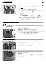
Remove the carburetor. (
700062-10
–
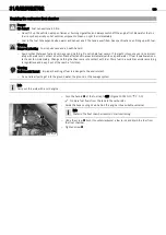
Check the throttle slide opening using a wire or a drill shank.
Throttle slide opening
1
mm (0.04
in)
» If the throttle slide opening does not equal the specified value:
–
Adjust the throttle slide opening with adjusting screw
.
21.16
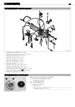
Checking/adjusting the float level
700061-10
–
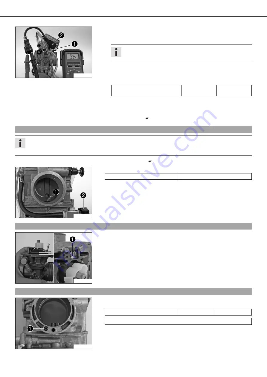
Hold the carburetor at a slant, securing the pin against falling out of the float.
–
Hold the carburetor at a slant so that the float lies against the float needle valve
but does not press it together.
» In this position, if the edge on the float is not parallel to the sealing area of the
float chamber:
–
Adjust the float level by bending float lever
.
21.17
Assembling the carburetor
700049-11
–
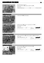
Mount and tighten idle air jet
.
Specification
Idle air jet
M4,5x0.75
2
Nm (1.5
lbf
ft)
Idle air jet
(100)

