background image

OWNER'S MANUAL

2019

390 Duke

Art. no. 3213939en

Summary of Contents for 390 Duke AR 2019

Page 1: ...OWNER S MANUAL 2019 390 Duke Art no 3213939en ...

Page 2: ......

Page 3: ...rint However minor differences due to further developments in design cannot be ruled out completely All specifications are non binding KTM Sportmotorcycle GmbH specifically reserves the right to modify or delete technical specifications prices colors forms materials services designs equipment etc without prior notice and without specifying reasons to adapt these to local conditions as well as to s...

Page 4: ...national quality management standard Issued by TÜV Management Service KTM Sportmotorcycle GmbH Stallhofnerstraße 3 5230 Mattighofen Austria This document is valid for the following models 390 Duke EU F4303S1 F4303S2 390 Duke B D EU F4303S3 F4303S4 390 Duke AU F4360S1 F4360S2 390 Duke JP F4386S1 F4386S2 390 Duke AR F4342S1 F4342S2 390 Duke BR F4340S1 F4340S2 390 Duke CN F4387S1 F4387S2 390 Duke CO ...

Page 5: ...ces 17 3 3 Spare parts accessories 17 3 4 Service 18 3 5 Figures 18 3 6 Customer service 18 4 VIEW OF VEHICLE 20 4 1 View of vehicle front left example 20 4 2 View of vehicle rear right example 22 5 SERIAL NUMBERS 24 5 1 Vehicle identification number 24 5 2 Type label 24 5 3 Engine number 25 5 4 Key number 26 6 CONTROLS 27 6 1 Clutch lever 27 6 2 Hand brake lever 27 6 3 Throttle grip 28 6 4 Switch...

Page 6: ... 50 7 7 Speed 52 7 8 Shift warning light 52 7 9 Speed 53 7 10 ODO display 54 7 11 Coolant temperature indicator 54 7 12 Fuel level display 55 7 13 Time 56 7 14 Favourites display 57 7 15 Quick Selector 1 display 57 7 16 Quick Selector 2 display 58 7 17 Menu 58 7 17 1 KTM MY RIDE optional 59 7 17 2 Info 60 7 17 3 Motorcycle 60 7 17 4 Settings 61 7 17 5 Preferences 61 7 17 6 Pairing optional 62 7 17...

Page 7: ...3 9 7 Transport 104 9 8 Refueling 106 10 SERVICE SCHEDULE 109 10 1 Additional information 109 10 2 Required work 109 10 3 Recommended work 111 11 TUNING THE CHASSIS 113 11 1 Adjusting the spring preload of the shock absorber 113 11 2 Adjusting the shift lever 114 12 SERVICE WORK ON THE CHASSIS 116 12 1 Raising the motorcycle with rear lifting gear 116 12 2 Removing the rear of the motorcycle from ...

Page 8: ...free travel of foot brake lever 145 13 8 Adjusting the free travel of the foot brake lever 147 13 9 Checking the rear brake fluid level 149 13 10 Adding rear brake fluid 150 13 11 Checking the rear brake linings 153 14 WHEELS TIRES 155 14 1 Removing the front wheel 155 14 2 Installing the front wheel 156 14 3 Removing the rear wheel 158 14 4 Installing the rear wheel 160 14 5 Checking the rear hub...

Page 9: ... Changing the engine oil and oil filter cleaning the oil screens 203 18 3 Adding engine oil 207 19 CLEANING CARE 209 19 1 Cleaning the motorcycle 209 19 2 Checks and maintenance steps for winter operation 212 20 STORAGE 214 20 1 Storage 214 20 2 Preparing for use after storage 216 21 TROUBLESHOOTING 217 22 TECHNICAL DATA 220 22 1 Engine 220 22 2 Engine tightening torques 221 22 3 Capacities 225 22...

Page 10: ...5 AUXILIARY SUBSTANCES 242 26 STANDARDS 244 27 INDEX OF SPECIAL TERMS 245 28 LIST OF ABBREVIATIONS 246 29 LIST OF SYMBOLS 247 29 1 Red symbols 247 29 2 Yellow and orange symbols 247 29 3 Green and blue symbols 247 INDEX 249 ...

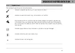
Page 11: ...with this symbol requires specialist knowledge and technical understanding In the interest of your own safety have these jobs performed by an authorized KTM workshop Your motorcycle will be optimally cared for there by specially trained experts using the auxiliary tools required Indicates a page reference more information is provided on the specified page Indicates information with more details or...

Page 12: ... rework 1 2 Formats used The typographical formats used in this document are explained below Proprietary name Indicates a proprietary name Name Indicates a protected name Brand Indicates a brand available on the open market Underlined terms Refer to technical details of the vehicle or indicate technical terms which are explained in the glossary ...

Page 13: ...le property and the environment through use not as intended Any use of the vehicle beyond the intended and defined use constitutes misuse Misuse also includes the use of operating and auxiliary fluids which do not meet the required specification for the respective use 2 3 Safety advice A number of safety instructions need to be followed to operate the product described safely Therefore read this i...

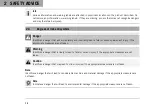
Page 14: ...invariably lead to fatal or serious permanent injury if the appropriate measures are not taken Warning Identifies a danger that is likely to lead to fatal or serious injury if the appropriate measures are not taken Caution Identifies a danger that may lead to minor injuries if the appropriate measures are not taken Note Identifies a danger that will lead to considerable machine and material damage...

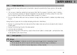
Page 15: ... rendered inoperative by any person Among those acts presumed to constitute tampering are the acts listed below 1 Removal or puncturing of the main silencers baffles header pipes or any other components which conduct exhaust gases 2 Removal or puncturing of parts of the intake system 3 Lack of proper maintenance 4 Replacing moving parts of the vehicle or parts of the exhaust system or intake syste...

Page 16: ...before you perform any work on the vehicle Only operate the vehicle when it is in perfect technical condition in accordance with its intended use and in a safe and environmentally compatible manner An appropriate driver s license is needed to ride the vehicle on public roads Have malfunctions that impair safety promptly eliminated by an authorized KTM workshop Adhere to the information and warning...

Page 17: ...hat are to be reused and check them for damage and wear Change damaged or worn parts After completing a repair or service work check the operating safety of the vehicle 2 9 Environment If you use your motorcycle responsibly you can ensure that problems and conflicts do not occur To protect the future of the motorcycle sport make sure that you use your motorcycle legally display environmental consc...

Page 18: ...use and how you can protect yourself from injury Keep the Owner s Manual in an accessible place to enable you to refer to it as needed If you would like to know more about the vehicle or have questions on the material you read please contact an authorized KTM dealer The Owner s Manual is an important component of the vehicle and must be handed over to the new owner if the vehicle is sold The Owner...

Page 19: ...nd in the Service Warranty Booklet 3 2 Fuel auxiliary substances Note Environmental hazard Improper handling of fuel is a danger to the environment Do not allow fuel to enter the groundwater the soil or the sewage system Use fuels and auxiliary substances in accordance with the Owner s Manual and specification 3 3 Spare parts accessories For your own safety only use spare parts and accessory produ...

Page 20: ...r of components such as the drive train brake system or suspension components For this reason it may be necessary to inspect or replace parts before the next scheduled service It is imperative that you adhere to the stipulated run in times and service intervals If you observe these exactly you will ensure a much longer service life for your motorcycle 3 5 Figures The figures contained in the manua...

Page 21: ...IMPORTANT NOTES 3 19 A list of authorized KTM dealers can be found on the KTM website International KTM Website http www ktm com ...

Page 22: ...4 VIEW OF VEHICLE 20 4 1 View of vehicle front left example V01275 10 ...

Page 23: ...VIEW OF VEHICLE 4 21 1 Combination instrument 2 Clutch lever p 27 3 Front rider s seat 4 Passenger seat 5 Grab handles p 38 6 Seat lock p 37 7 Shift lever p 39 8 Side stand p 40 9 Engine number p 25 ...

Page 24: ...4 VIEW OF VEHICLE 22 4 2 View of vehicle rear right example V01276 10 ...

Page 25: ...n signal switch p 30 2 Horn button p 31 3 Ignition and steering lock p 32 4 Emergency OFF switch p 31 4 Electric starter button p 32 5 Throttle grip p 28 6 Hand brake lever p 27 7 Vehicle identification number p 24 7 Type label p 24 8 Foot brake lever p 40 9 Passenger foot pegs p 38 ...

Page 26: ...ntification number 402408 10 The vehicle identification number 1 is stamped on the right side of the steering head 5 2 Type label 402174 10 EU JP AR BR CN CO MY PH TH The type label 1 is on the right of the frame behind the steering head ...

Page 27: ...S 5 25 402772 10 390 Duke AU The type label 1 is on the left of the frame behind the steer ing head 5 3 Engine number 402486 10 The engine number 1 is stamped on the left side of the engine under the engine sprocket ...

Page 28: ...e found on the KEYCODECARD Info You need the key number to order a spare key Keep the KEYCODECARD in a safe place If at least one ignition key is still available a spare key can be produced If an ignition key is no longer present the entire lock system must be replaced ...

Page 29: ...er F00783 10 The clutch lever 1 is fitted on the left side of the handlebar 6 2 Hand brake lever F00784 10 The hand brake lever 1 is fitted on the right side of the handle bar The front brake is engaged using the hand brake lever ...

Page 30: ...ttle grip F00784 11 The throttle grip 1 is fitted on the right side of the handlebar 6 4 Switches on the left side of the handlebar 6 4 1 Combination switch The combination switch is fitted on the left side of the handlebar ...

Page 31: ...tch F00786 10 Light switch 1 is fitted on the left side of the handlebar Possible states Low beam on Light switch in position A In this position the low beam and the tail light are switched on High beam on Push the light switch to position B In this position the high beam and the tail light are switched on Headlight flasher Push the light switch into posi tion C ...

Page 32: ...4 is the BACK button 6 4 4 Turn signal switch F00787 11 Turn signal switch 1 is fitted on the left side of the handlebar Possible states Turn signal off Turn signal switch pushed toward the switch housing Left turn signal on Turn signal switch pressed to the left The turn signal switch returns automatically to the central position after use Right turn signal on Turn signal switch pressed to the ri...

Page 33: ...6 5 Switches on the right side of the handlebar 6 5 1 Emergency OFF switch F00784 12 The emergency OFF switch 1 is fitted on the right side of the handlebar Possible states Emergency OFF switch off In this position the igni tion circuit is interrupted a running engine stops and a non running engine cannot be started Emergency OFF switch on This position is required for operation the ignition circu...

Page 34: ... position the starter motor is actuated 6 6 Ignition and steering lock F00788 01 The ignition and steering lock is located in front of the upper triple clamp Possible states Ignition off OFF In this position the ignition circuit is interrupted a running engine stops and a non running engine will not start The ignition key can be removed Ignition on ON In this position the ignition circuit is close...

Page 35: ... Locking the steering Note Danger of damage The parked vehicle can roll away or fall over Park the vehicle on a firm and level surface 400732 01 Park the vehicle Turn the handlebar all the way to the left Insert the ignition key into the ignition and steering lock press in and turn to the left Remove the ignition key Steering is no longer possible ...

Page 36: ... fuel tank filler cap Danger Fire hazard Fuel is highly flammable The fuel in the fuel tank expands when warm and can escape if overfilled Do not refuel the vehicle in the vicinity of open flames or lit cigarettes Switch off the engine for refueling Make sure that no fuel is spilled particularly not on hot parts of the vehicle If any fuel is spilled wipe it off immediately Observe the specificatio...

Page 37: ... clothing in case of fuel spills on them Keep fuels correctly in a suitable canister and out of the reach of children Note Environmental hazard Improper handling of fuel is a danger to the environment Do not allow fuel to enter the groundwater the soil or the sewage system F00858 10 Lift cover 1 of the fuel tank filler cap and insert the ignition key into the lock Note Danger of damage The ignitio...

Page 38: ...ocked cor rectly after closing Change your clothing if fuel spills on them Rinse the affected area immediately with plenty of water in the event of contact with the skin Fold down the fuel tank filler cap Turn the ignition key 90 clockwise Push down the fuel tank filler cap and turn the ignition key counterclockwise until the fuel tank filler cap lock engages Remove the ignition key and close the ...

Page 39: ... 6 37 6 11 Seat lock F00790 10 The seat lock 1 is located to the left of the seat The seat lock can be unlocked using the ignition key 6 12 Tool set F00729 10 The tool set 1 is located under the passenger seat ...

Page 40: ...u carry a passenger the passenger can hold onto the grab handles during the trip 6 14 Passenger foot pegs F00866 10 The passenger foot pegs can be folded up and down Possible states Passenger foot pegs folded up For operation without a pas senger Passenger foot pegs folded down For operation with a pas senger ...

Page 41: ... 39 6 15 Shift lever 401950 10 Shift lever 1 is mounted on the left side of the engine 401950 11 The gear positions can be seen in the photograph The neutral or idle position is between the first and second gears ...

Page 42: ...2029 10 The side stand 1 is located on the left of the vehicle The side stand is used for parking the motorcycle Info The side stand must be folded up during motorcycle use The side stand is coupled with the safety starting system follow the riding instructions Possible states Side stand folded out The vehicle can be supported on the side stand The safety starting system is active ...

Page 43: ...CONTROLS 6 41 Side stand folded in This position is mandatory when riding the motorcycle The safety starting system is inactive ...

Page 44: ...ction areas 1 indicator lamps p 46 Display 2 7 2 Activation and test F00876 01 Activation The combination instrument is activated when the ignition is switched on Info The brightness of the displays is controlled by an ambient light sensor in the combination instrument Test The welcome text appears on the display and the indicator lamps are briefly activated for a function check ...

Page 45: ...ent light sensor in the combination instrument measures the brightness of the environment The display is brightened darkened or switched to the other mode depending on the light intensity measured by the ambient light sensor The display mode can be configured in the Display Theme menu Here you can select automatic day night mode or permanent night mode ...

Page 46: ...eir relevance Yellow warnings 1 indicate errors or information which require prompt intervention or an adjustment to the riding style Red warnings 2 indicate errors or information which require immediate intervention Info Warnings can be hidden by pressing any button All the existing warnings are displayed in the Warning menu until they are no longer active ...

Page 47: ...COMBINATION INSTRUMENT 7 45 ...

Page 48: ...7 COMBINATION INSTRUMENT 46 7 5 Indicator lamps F00900 01 ...

Page 49: ...run ning and the oil pressure warning lamp lights up stop immediately taking care not to endanger yourself or other road users in the process and switch off the engine The ABS warning lamp lights up until a speed of approx 6 km h approx 4 mph or more has been reached Possible states The turn signal indicator lamp flashes green simultaneously with the turn signal The turn signal is switched on Malf...

Page 50: ...rself or other road users in the process and switch off the engine Alarm system indicator lamp flashes red Status message on the alarm system optional The high beam indicator lamp lights up blue The high beam is switched on The general warning lamp lights up yellow A note warning note on operating safety has been detected This is shown in addition ...

Page 51: ...COMBINATION INSTRUMENT 7 49 ...

Page 52: ...7 COMBINATION INSTRUMENT 50 7 6 Display M01580 11 ...

Page 53: ...he tachometer display 2 Gear display 3 Unit for the speed display 4 Speed p 53 5 Unit for the speedometer 6 ODO display p 54 7 ABS mode 8 Coolant temperature indicator p 54 9 Fuel level display p 55 bk Bluetooth optional bl Time p 56 bm SET Only shown where the menu overview is closed bn Favourites display p 57 ...

Page 54: ...ed for the shift warning light can be set The shift warning light is always active during the running in phase up to 1 000 km 621 mi The shift warning light can only be deactivated and the values for RPM1 and RPM2 can only be adjusted after this In RPM1 the shift warning light flashes and in RPM2 it flashes and the color changes Info In sixth gear the shift warning light is deactivated when the en...

Page 55: ...i The shift warning light always flashes at 6 500 rpm Coolant temperature 35 C 95 F ODO 1 000 km 620 mi RPM1 shift warning light flashes RPM2 shift warning light flashes and changes color 7 9 Speed M01581 11 Speed 1 is shown in kilometers per hour km h or in miles per hour mph ...

Page 56: ...02808 01 The coolant temperature indicator consists of bars The more bars that light up the hotter the coolant Note Engine failure Overheating damages the engine If the coolant temperature warning is displayed stop imme diately and take care not to endanger yourself or other traffic participants in the process Allow the engine and cooling system to cool down Check and if necessary correct the cool...

Page 57: ...Possible states The engine is cold Up to three bars light up Engine warm Four to five bars light up Engine hot Six to eight bars light up Engine very hot All eight bars light up red 7 12 Fuel level display 402807 10 The fuel tank contents are shown in area 1 of the display The fuel level indicator consists of bars The more bars are lit the more fuel is in the fuel tank ...

Page 58: ...is folded up and the emergency OFF switch is switched on the fuel level display is next updated after 2 minutes The fuel level display flashes if the combination instrument does not receive a signal from the fuel level sensor 7 13 Time M01581 13 The time is shown in area 1 of the display The time is displayed in 24 hour format in all languages except for EN US The time is displayed in 12 hour form...

Page 59: ...four items of information selected are displayed on two lines Five to eight items of information selected are displayed on a single line 7 15 Quick Selector 1 display E01065 01 When the menu is closed the Quick Selector 1 menu is opened by pressing the UP button Press the BACK button to close Quick Selector 1 Info The Quick Selector 1 can be configured in the Quick Selec tor 1 menu Any information...

Page 60: ...BACK button to close Quick Selector 2 Info The Quick Selector 2 can be configured in the Quick Selec tor 2 menu Any information can be selected 7 17 Menu F00906 10 Info Press the SET button 1 in the start screen to open the menu Navigate through the menu using the UP button 2 or the DOWN button 3 Press the BACK button 4 to close the current menu or the menu overview ...

Page 61: ...T button when the menu is closed Press the UP or DOWN button until KTM MY RIDE is marked Press the SET button to open the menu In the KTM MY RIDE menu an appropriate cellphone or appropriate headset can be paired with the combination instrument via Blue tooth Info Not every cellphone and headset is suitable for pairing with the combination instrument The standard Bluetooth 2 1 must be supported ...

Page 62: ...d Press the SET button to open the menu General information can be accessed in Info 7 17 3 Motorcycle V01162 01 Condition The motorcycle is stationary Press the SET button when the menu is closed Press the UP or DOWN button until Motorcycle is marked Press the SET button to open the menu The vehicle drive mode can be configured in Motorcycle ...

Page 63: ... Favorites and quick selection can be configured in Settings 7 17 5 Preferences V01164 01 Condition The motorcycle is stationary Press the SET button when the menu is closed Press the UP or DOWN button until Preferences is marked Press the SET button to open the menu The combination instrument display can be configured in Prefer ences Settings can be made for units or various values Several functi...

Page 64: ...ress the UP or DOWN button until Pairing is marked Press the SET button to open the menu A suitable cellphone or headset can be paired with the combina tion instrument via Bluetooth in the Pairing menu Info The Bluetooth function can only be used in conjunction with KTM MY RIDE optional When the Bluetooth function is switched on and the device is connected the Bluetooth symbol appears in the displ...

Page 65: ...KTM MY RIDE is marked Press the SET button to open the menu Press the UP or DOWN button until Pairing is marked Press the SET button to open the menu Press the UP or DOWN button until Phone is marked Press the SET button to open the menu Info Two cellphones can never be paired simultaneously with the combination instrument Press the UP or DOWN button until Pairing is marked Press the SET button to...

Page 66: ...ng the Passkey on the cellphone and on the combination instrument Info Once the pairing is completed the registered trademark of the paired cellphone is displayed in the Phone menu Press the UP or DOWN button until the paired device is marked The paired device can be deleted by pressing the SET button Not every cellphone is suitable for pairing with the combination instrument Move the previously p...

Page 67: ...ction KTM MY RIDE optional activated Function Bluetooth optional activated The Bluetooth function should also be activated in the device to be paired Press the SET button when the menu is closed Press the UP or DOWN button until KTM MY RIDE is marked Press the SET button to open the menu Press the UP or DOWN button until Pairing is marked Press the SET button to open the menu Press the UP or DOWN ...

Page 68: ...iring mode for the headset to be found by the combination instrument Follow the instructions in the Owner s Manual of the headset Once the pairing is completed the name of the paired headset is displayed in the Headset menu Press the UP or DOWN button until the paired device is marked The paired device can be deleted by pressing the SET button Not every headset is suitable for pairing with the com...

Page 69: ...5 01 Condition Function KTM MY RIDE optional activated Function Bluetooth optional activated The Bluetooth function should also be activated in the device to be paired Press the SET button when the menu is closed Press the UP or DOWN button until KTM MY RIDE is marked Press the SET button to open the menu Warning Danger of accidents Headphone volume which is too high distracts attention from traff...

Page 70: ... the audio volume Press and hold the DOWN button to reduce the audio volume Press the UP button briefly to change to the next audio track Press the DOWN button briefly to change to the previous audio track Press the SET button to play or pause the audio track Info The audio function can be added to Quick Selector 1 or Quick Selector 2 for easier operation ...

Page 71: ...one volume which is too high distracts attention from traffic activity Always select headphone volume which is low enough for you to still clearly hear acoustic signals Press the SET button to accept an incoming call Press the BACK button to reject an incoming call Press and hold the UP button to increase the audio volume Press and hold the DOWN button to reduce the audio volume Info The call dura...

Page 72: ...17 12 Trip 1 E01062 01 Press the SET button when the menu is closed Press the UP or DOWN button until Info is marked Press the SET button to open the menu Press the UP or DOWN button until Trip 1 is marked Press the SET button to open the menu Trip shows the distance since the last reset such as between two refueling stops Trip is running and counts up to 9999 ØCons indicates the average fuel cons...

Page 73: ...tton to open the menu Press the UP or DOWN button until Trip 2 is marked Press the SET button to open the menu Trip shows the distance since the last reset such as between two refueling stops Trip is running and counts up to 9999 ØCons indicates the average fuel consumption based on Trip ØSpeed indicates the average speed based on Trip and Trip Time Trip Time shows the journey time on the basis of...

Page 74: ... is present Press the SET button when the menu is closed Press the UP or DOWN button until Info is marked Press the SET button to open the menu Press the UP or DOWN button until Warning is marked Press the SET button to open the menu Use the UP or DOWN button to navigate through the warnings In the Warning menu all warnings that have occurred are dis played and stored ...

Page 75: ...o open the menu Activate menu item using the UP or DOWN button Press the SET button to select between ABS modes Info If the ABS mode Road is enabled ABS controls both wheels If the ABS mode Super Moto is enabled ABS only con trols the front wheel The rear wheel is not controlled by ABS and may lock during braking maneuvers The ABS warning lamp flashes slowly to remind you that the Super Moto ABS m...

Page 76: ... menu item and select it with the SET button Up to eight items of information can be selected in the Favourites menu 7 17 17 Quick Selector 1 V01169 01 Condition The motorcycle is stationary Press the SET button when the menu is closed Press the UP or DOWN button until Settings is marked Press the SET button to open the menu Press the UP or DOWN button until Quick Selector 1 is marked Press the SE...

Page 77: ...losed Press the UP or DOWN button until Settings is marked Press the SET button to open the menu Press the UP or DOWN button until Quick Selector 2 is marked Press the SET button to open the menu Press the UP or DOWN button to activate the menu item and select it with the SET button Information can be selected in the Quick Selector 2 menu When the menu is closed the Quick Selector 2 menu is opened...

Page 78: ...enu Press the UP or DOWN button until Bluetooth is marked Press the SET button to open the menu Activate the menu item using the UP or DOWN button Press the SET button to switch the Bluetooth function on or off Info The Bluetooth function can only be used in conjunction with KTM MY RIDE optional When the Bluetooth function is switched on and the device is connected the Bluetooth symbol appears in ...

Page 79: ...arked Press the SET button to open the menu Press the UP or DOWN button until Display Theme is marked Press the SET button to open the menu Activate the menu item using the UP or DOWN button Press the SET button to set up automatic day night mode or permanent night mode Info In both modes the display is brightened or dimmed depending on the amount of light that the ambient light sensor detects ...

Page 80: ... or DOWN button until Shift Light is marked Press the SET button to open the menu Activate the menu item using the UP or DOWN button Switch the shift warning light on or off or set the engine speed for the gear shift recommendation by pressing the SET button Info When the engine speed reaches RPM 1 the speed dis play lights up red When the engine speed reaches RPM 2 the speed dis play flashes red ...

Page 81: ...Clock Date is marked Press the SET button to open the menu V01173 01 Setting the clock Press the UP or DOWN button until the time is marked Press the SET button The hour flashes and is underlined Press the UP or DOWN button until the current hour is set Press the SET button The minutes flash and are underlined Press the UP or DOWN button until the current minute is set Press the SET button The tim...

Page 82: ... and is underlined Press the UP or DOWN button until the current day is set Press the SET button The month flashes and is underlined Press the UP or DOWN button until the current month is set Press the SET button The year flashes and is underlined Press the UP or DOWN button until the current year is set Press the SET button The date is stored ...

Page 83: ...unning light is not a substitute for the low beam Automatic switching between the daytime running light and low beam may only be partially available when visibility is significantly impaired due to fog snow or rain Ensure that the appropriate type of lighting is always selected If necessary switch off the daytime running lights using the menu before going on a ride or when stopped so that the low ...

Page 84: ...Condition The motorcycle is stationary Press the SET button when the menu is closed Press the UP or DOWN button until Preferences is marked Press the SET button to open the menu Press the UP or DOWN button until Units is marked Press the SET button to open the menu Press the UP or DOWN button until Distance is marked Press the SET button to open the menu Activate the menu item using the UP or DOWN...

Page 85: ... until Temperature is marked Press the SET button to open the menu Activate the menu item using the UP or DOWN button Press the SET button to confirm the desired unit 7 17 26 Fuel Cons V01177 01 Condition The motorcycle is stationary Press the SET button when the menu is closed Press the UP or DOWN button until Preferences is marked Press the SET button to open the menu Press the UP or DOWN button...

Page 86: ...Press the SET button when the menu is closed Press the UP or DOWN button until Preferences is marked Press the SET button to open the menu Press the UP or DOWN button until Language is marked Press the SET button to open the menu Press the UP or DOWN button to activate the menu item and select it with the SET button The menu languages are US English UK English German Italian French and Spanish ...

Page 87: ...ext service due is shown in the Service menu 7 17 29 Extra Functions V01180 01 Condition The motorcycle is stationary Motorcycle with optional supplementary function Press the SET button when the menu is closed Press the UP or DOWN button until Preferences is marked Press the SET button to open the menu Press the UP or DOWN button until Extra Functions is marked Press the SET button to open the me...

Page 88: ...7 COMBINATION INSTRUMENT 86 Info The current KTM PowerParts and the available software for your vehicle can be found on the KTM website ...

Page 89: ...met boots gloves as well as trousers and a jacket with protectors on all rides Always wear protective clothing that is in good condition and meets the legal regulations Warning Danger of crashing Different tire tread patterns on the front and rear wheel impair the handling charac teristic Different tire tread patterns can make the vehicle significantly more difficult to control Make sure that only...

Page 90: ...as been carried out by an authorized KTM workshop The delivery certificate and the Service and Manufacturer Warranty booklet must be transferred with the vehicle Read the entire Owner s Manual before riding for the first time Get to know the controls Get used to the handling characteristic of the motorcycle on suitable terrain before undertaking a more chal lenging ride Also ride as slowly as poss...

Page 91: ... warning light is set to a specified value and cannot be changed Avoid fully opening the throttle 8 3 Loading the vehicle Warning Danger of accidents Total weight and axle loads influence the handling characteristic The total weight consists of motorcycle ready for operation and with a full tank driver and passenger with protective clothing and helmet and luggage Do not exceed the maximum permissi...

Page 92: ...en mounting cases Warning Danger of accidents Luggage which has slipped impairs visibility If the tail light is covered you are less visible to traffic behind you especially when it is dark Check that your luggage is fixed properly at regular intervals Warning Danger of accidents A high payload alters the handling characteristic and increases the stopping distance Adapt your speed to your payload ...

Page 93: ...e vehicle and ensure even weight distribution between the front and rear wheels Do not exceed maximum permissible weight and maximum permissible axle loads Guideline Maximum permissible overall weight 355 kg 783 lb Maximum permissible front axle load 127 kg 280 lb Maximum permissible rear axle load 228 kg 503 lb ...

Page 94: ...ke fluid level p 149 Check the front brake linings p 144 Check the rear brake linings p 153 Check that the brake system is functioning properly Check the coolant level p 190 Check for chain dirt accumulation p 125 Check the chain tension p 127 Check the tire condition p 165 Check tire pressure p 167 Check the settings of all controls and ensure that they can be operated smoothly Check that the ele...

Page 95: ... Electronic components and safety devices will be damaged if the 12 V battery is dis charged or missing Never operate the vehicle with a discharged 12 V battery or without a 12 V battery Note Engine damage Unfiltered intake air has a negative effect on the service life of the engine Dust and dirt will enter the engine without an air filter Never start to use the vehicle without an air filter Note ...

Page 96: ... on the ignition by turning the ignition key to the posi tion After you switch on the ignition you can hear the fuel pump working for about two seconds The function check of the combination instrument is run at the same time Shift the transmission to neutral position The green idle indicator lamp N lights up The ABS indicator lamp lights up and goes back out after starting off Press the electric s...

Page 97: ... before trying again This motorcycle is equipped with a safety starting sys tem You can only start the engine if the transmission is in neutral or if the clutch lever is pulled when a gear is engaged If the side stand is folded out and you shift into gear and release the clutch lever the engine stops 9 3 Starting off Pull the clutch lever engage 1st gear release the clutch lever slowly and simulta...

Page 98: ...g Danger of accidents If you change down at high engine speed the rear wheel blocks and the engine races Do not change into a low gear at high engine speed Warning Danger of accidents An incorrect ignition key position causes malfunctions Do not change the ignition key position while driving Warning Danger of accidents Adjustments to the vehicle distract attention from traffic activity Make all ad...

Page 99: ...ning Danger of accidents A risky riding style constitutes a major risk Comply with traffic regulations and ride defensively and with foresight to detect sources of danger as early as possible Warning Danger of accidents Cold tires have reduced road grip Ride the first miles carefully on every journey at moderate speed until the tires reach operating tem perature Warning Danger of accidents New tir...

Page 100: ... use Note Engine failure Overheating damages the engine If the coolant temperature warning is displayed stop immediately and take care not to endanger yourself or other traffic participants in the process Allow the engine and cooling system to cool down Check and if necessary correct the coolant level on the cooling system while it is in a cooled state Info If unusual noises occur while riding sto...

Page 101: ... reaching maximum speed by fully opening the throttle grip turn the throttle back so it is open This will barely reduce the speed but fuel consumption will be considerably lower Accelerate only up to a speed suitable for the road surface and weather conditions Particularly in bends do not shift and accelerate very carefully Brake if necessary and close the throttle at the same time in order to shi...

Page 102: ...ction indicator lamp lights up during a trip please contact an authorized KTM workshop as soon as possi ble If the general warning lamp lights up during a trip an oper ating safety warning message was detected Info All warnings which have occurred are displayed and stored in the Warning menu until these are no longer active 9 5 Applying the brakes Warning Danger of accidents Moisture and dirt impa...

Page 103: ...ot brake lever when you are not braking Warning Danger of accidents Higher total weight increases the stopping distance Take the longer stopping distance into account when carrying a passenger or luggage with you Warning Danger of accidents Salt on the roads impairs the brake system Brake carefully several times to remove salt from the brake linings and the brake discs Warning Danger of accidents ...

Page 104: ...l braking or if you brake on a slippery ground Warning Danger of accidents Banked or laterally sloping ground reduces the maximum possible delay If possible finish braking before going into a bend Always finish braking before you go into a bend Shift down to a lower gear appropriate to your speed Use the braking effect of the engine on long downhill stretches Shift back one or two gears but do not...

Page 105: ...hen the vehicle is operated Do not touch any parts such as the exhaust system radiator engine shock absorber or brake system before the vehicle parts have cooled down Let the vehicle parts cool down before you perform any work on the vehicle Note Material damage The vehicle may be damaged by incorrect procedure when parking Significant damage may be caused if the vehicle rolls away or falls over T...

Page 106: ...e is switched off with the emergency OFF switch and the ignition remains switched on at the ignition lock power continues to flow to most power consumers and the 12 V battery will dis charge You should therefore always switch off the engine with the ignition lock the emergency OFF switch is intended for emergencies only Park the motorcycle on a firm surface Swing the side stand forward with your f...

Page 107: ... risk Do not park the vehicle near to materials which are highly flammable or explosive Allow the vehicle to cool down before covering it 401448 01 Switch off the engine and remove the ignition key Use tension belts or other suitable devices to secure the motorcycle against accidents or falling over ...

Page 108: ...lled wipe it off immediately Observe the specifications for refueling Warning Danger of poisoning Fuel is poisonous and a health hazard Avoid skin eye and clothing contact with fuel Immediately consult a doctor if you swallow fuel Do not inhale fuel vapors In case of skin contact rinse the affected area with plenty of water Rinse the eyes thoroughly with water and consult a doctor in case of fuel ...

Page 109: ...t This will result in problems with the fuel system Refuel only with clean fuel that meets the specified standards Your authorized KTM workshop will be glad to help Note Environmental hazard Improper handling of fuel is a danger to the environment Do not allow fuel to enter the groundwater the soil or the sewage system ...

Page 110: ... 1 of the fuel filler Total fuel tank capacity approx 13 5 l 3 57 US gal Super unleaded ROZ 95 RON 95 PON 91 p 240 EU AU JP AR CN CO MY PH Total fuel tank capacity approx Gasohol 95 E20 RON 95 p 240 390 Duke TH Total fuel tank capacity approx Super unleaded type C ROZ 95 RON 95 PON 91 p 241 390 Duke BR Close the fuel tank filler cap p 36 ...

Page 111: ...date service schedule can always be found on KTM Dealer net Your authorized KTM dealer will be happy to advise you 10 2 Required work Every two years Every year every 15 000 km 9 300 mi every 7 500 km 4 650 mi after 1 000 km 620 mi Read out the fault memory using the KTM diagnostics tool Check that the electrical system is functioning properly Change the engine oil and oil filter clean the oil scr...

Page 112: ...Check the chain rear sprocket and engine sprocket p 130 Check the chain tension p 127 Check the coolant level p 190 Check that the radiator fan is functioning properly Change the air filter clean the air filter box Check that the throttle cables are undamaged routed without sharp bends and set cor rectly Check the cables for damage and routing without sharp bends Check the valve clearance change t...

Page 113: ...e operation and take a test ride Read out the error memory after the test ride using the KTM diagnostics tool Set the service interval display Make the service entry in KTM Dealer net and in the Service Manufacturer Warranty booklet One time interval Periodic interval 10 3 Recommended work Every four years Every year every 30 000 km 18 600 mi every 7 500 km 4 650 mi after 1 000 km 620 mi Check the...

Page 114: ...play Check the wheel bearing for play Check the antifreeze Change the coolant p 196 Empty the drainage hoses Check all hoses e g fuel coolant bleeder drainage etc and sleeves for cracking leaks and incorrect routing Grease all moving parts e g side stand hand lever chain and check for smooth operation Check the screws and nuts for tightness One time interval Periodic interval ...

Page 115: ...preload defines the initial status of the spring operation on the shock absorber The best spring preload setting is achieved when it is set for the weight of the rider and that of any lug gage and a passenger thus ensuring an ideal compromise between handling and stability F00793 10 Adjust the spring preload by turning adjusting ring 1 Guideline Spring preload Standard 5 clicks Hook wrench shock a...

Page 116: ...sen nuts 1 Adjust the shift lever by turning shift rod 2 Guideline Shift rod adjustment range A 90 102 mm 3 54 4 02 in Info Make the same adjustments on both sides At least five screw threads must be screwed into the seating Check adjusting angle B Guideline Adjusting angle B shift rod bell crank shift lever 90 Tighten nuts 1 ...

Page 117: ...s have been tightened the bearings of the shift rod must be central and aligned identically to each other in order to ensure freedom of movement in the bearing shells Check the shift lever to ensure it is functioning properly and can move freely ...

Page 118: ...upports of the lifting gear Insert the adapter in the rear lifting gear Retaining adapter 61029955244 Rear wheel work stand 69329955000 Stand the motorcycle upright align the lifting gear to the link fork and the adapters and raise the motorcycle 12 2 Removing the rear of the motorcycle from the lifting gear Note Danger of damage The parked vehicle can roll away or fall over Park the vehicle on a ...

Page 119: ...fting gear and lean the vehicle on side stand 1 Remove bushings kit 12 3 Lifting the motorcycle with the front lifting gear Note Danger of damage The parked vehicle can roll away or fall over Park the vehicle on a firm and level surface Preparatory work Raise the motorcycle with the rear lifting gear p 116 ...

Page 120: ...emove protection cap 1 402345 01 Move the handlebar to the straight ahead position Position the lifting gear Mounting pin 69329965030 Front wheel work stand large 69329965100 Info Always raise the motorcycle at the rear first Lift the motorcycle at the front ...

Page 121: ... the motorcycle off the front lifting gear Note Danger of damage The parked vehicle can roll away or fall over Park the vehicle on a firm and level surface 402777 01 Main work Secure the motorcycle against falling over Remove the front lifting gear ...

Page 122: ...tion cap 1 Finishing work Remove the rear of the motorcycle from the lifting gear p 116 12 5 Cleaning the dust boots of the fork legs Preparatory work Raise the motorcycle with the rear lifting gear p 116 Lift the motorcycle with the front lifting gear p 117 ...

Page 123: ... oil seals behind can start to leak Warning Danger of accidents Oil or grease on the brake discs reduces the braking effect Always keep the brake discs free of oil and grease Clean the brake discs with brake cleaner when nec essary Clean and oil the dust boots and inner fork tubes of both fork legs Universal oil spray p 243 Press the dust boots back into their installation position Remove excess o...

Page 124: ...he motorcycle from the lifting gear p 116 12 6 Removing the passenger seat H01991 10 Insert the ignition key in seat lock 1 and turn it clockwise Raise the rear of the seat push it towards the rear and lift it off Remove the ignition key from the seat lock ...

Page 125: ...r ward Press passenger seat downward until it clicks into place Warning Danger of accidents The seat can come loose from the anchoring if it is not mounted correctly After assembly check whether the seat is correctly locked and cannot be pulled up Finally check that the passenger seat is correctly mounted 12 8 Removing the front rider s seat Preparatory work Remove the passenger seat p 122 ...

Page 126: ...ider s seat pull it towards the rear and remove it upwards 12 9 Mounting the front rider s seat H01994 01 Main work Attach the front rider s seat in area A and lower at the rear Finally check that the front rider s seat is correctly mounted Finishing work Mount the passenger seat p 123 ...

Page 127: ... chain p 125 12 11 Cleaning the chain Warning Danger of accidents Lubricants on the tires reduces the road grip Remove lubricants from the tires using a suitable cleaning agent Warning Danger of accidents Oil or grease on the brake discs reduces the braking effect Always keep the brake discs free of oil and grease Clean the brake discs with brake cleaner when necessary ...

Page 128: ...ons Info The service life of the chain depends largely on its maintenance Preparatory work Raise the motorcycle with the rear lifting gear p 116 400725 01 Main work Clean the chain regularly Rinse off loose dirt with a soft jet of water Remove old grease remains with chain cleaner Chain cleaner p 242 After drying apply chain spray Street chain spray p 243 Finishing work Remove the rear of the moto...

Page 129: ...ocket or the rear sprocket As a result the rear wheel locks or the engine will be damaged Check the chain tension regularly Set the chain tension in accordance with the specification Preparatory work Raise the motorcycle with the rear lifting gear p 116 M00714 10 Main work Shift the transmission to neutral position In the area after the chain sliding guard press the chain upward toward the link fo...

Page 130: ... the chain is tensioned too much the chain engine sprocket rear sprocket transmission and rear wheel bearings wear more quickly Some components may break if overloaded If the chain is too loose the chain may fall off the engine sprocket or the rear sprocket As a result the rear wheel locks or the engine will be damaged Check the chain tension regularly Set the chain tension in accordance with the ...

Page 131: ...at the markings on the left and right chain adjusters 4 are in the same position relative to the reference marks A The rear wheel is then correctly aligned Info The top chain section must be taut Chain wear is not always even so you should check the setting at different chain positions Tighten nuts 2 Make sure that chain adjusters 4 are fitted correctly on adjusting screws 3 Tighten nut 1 Guidelin...

Page 132: ... rear sprocket and engine sprocket Preparatory work Raise the motorcycle with the rear lifting gear p 116 100132 10 Main work Check the rear sprocket and engine sprocket for wear If the rear sprocket and engine sprocket are worn Change the drivetrain kit Info The engine sprocket rear sprocket and chain should always be replaced together ...

Page 133: ...he lower chain section Info Chain wear is not always even so you should repeat this measurement at different chain positions Maximum distance B from 20 chain rollers at the longest chain section 301 6 mm 11 874 in If distance B is greater than the specified measurement Change the drivetrain kit Info When a new chain is mounted the rear sprocket and engine sprocket should also be changed New chains...

Page 134: ...rew 1 is visi ble from above Change the chain sliding guard Check that the chain sliding guard is firmly seated If the chain sliding guard is loose Tighten the screw of the chain sliding guard Guideline Screw chain guard M5 7 Nm 5 2 lbf ft Loctite 243 Finishing work Remove the rear of the motorcycle from the lifting gear p 116 ...

Page 135: ...clutch lever F00783 11 Adjust the basic position of the clutch lever to your hand size by turning adjusting wheel 1 Info Push the clutch lever forward and turn the adjusting wheel Do not make any adjustments while riding 12 16 Removing the front spoiler F00796 10 Remove screws 1 ...

Page 136: ...12 SERVICE WORK ON THE CHASSIS 134 F00797 10 Remove screws 2 Take off the front spoiler 12 17 Fitting front spoiler F00796 10 Position the front spoiler Mount screws 1 but do not tighten yet ...

Page 137: ...SERVICE WORK ON THE CHASSIS 12 135 F00797 10 Mount and tighten screws 2 Guideline Screw front spoiler rear M6x9 9 Nm 6 6 lbf ft Tighten screws 1 Guideline Screw front spoiler M6x13 9 Nm 6 6 lbf ft ...

Page 138: ...ith the front brake applied away from public road traffic if the ABS is switched off Do not make any changes to the suspension travel Only use spare parts on the brake system which have been approved and recommended by KTM Only use tires wheels approved by KTM with the corre sponding speed index Maintain specified tire pressure Ensure that service work and repairs are performed professionally Your...

Page 139: ... like a conventional brake system without ABS When the ABS con trol unit detects a locking tendency in a wheel ABS begins reg ulating the brake pressure The control function causes a slight pulsing of the hand and foot brake levers The ABS warning lamp 3 must light up after the ignition is switched on and go out after starting off If it does not go out after starting off or if it lights up while r...

Page 140: ... off 13 2 Adjusting the basic position of the hand brake lever F00784 13 Adjust the basic position of the hand brake lever to your hand size by turning adjusting wheel 1 Info Push the hand brake lever forward and turn the adjust ing wheel Do not make any adjustments while riding 13 3 Checking the brake discs Warning Danger of accidents Worn out brake discs reduce the braking effect Make sure that ...

Page 141: ...1 of the brake linings Brake discs wear limit front 4 5 mm 0 177 in rear 3 6 mm 0 142 in If the brake disc thickness is less than the specified value Change the front brake disc Change the rear brake disc Check the front and rear brake discs for damage cracking and deformation If the brake disc exhibits damage cracking or deforma tion Change the front brake disc Change the rear brake disc ...

Page 142: ...until the problem is eliminated Your authorized KTM workshop will be glad to help Warning Danger of accidents Old brake fluid reduces the braking effect Make sure that brake fluid for the front and rear brake is changed in accordance with the service schedule Your authorized KTM workshop will be glad to help F00798 10 Move the brake reservoir mounted on the handlebar into a hori zontal position Ch...

Page 143: ...will be glad to help Warning Skin irritation Brake fluid causes skin irritation Keep brake fluid out of the reach of children Wear suitable protective clothing and safety glasses Do not allow brake fluid to come into contact with the skin the eyes or clothing Consult a doctor immediately if brake fluid has been swallowed Rinse the affected area with plenty of water in the event of contact with the...

Page 144: ...substances cause environmental damage Dispose of oils grease filters fuel cleaning agents brake fluid etc correctly and in compliance with the applicable regulations Info Never use DOT 5 brake fluid It is silicone based and purple in color Oil seals and brake lines are not designed for DOT 5 brake fluid Avoid contact between brake fluid and painted parts Brake fluid attacks paint Only use clean br...

Page 145: ...ontal position Remove screws 1 Take off cover 2 with membrane 3 Add brake fluid to level A Guideline Dimension A 5 mm 0 2 in Brake fluid DOT 4 DOT 5 1 p 238 Position the cover with the membrane Mount and tighten the screws Info Immediately clean up any brake fluid that has over flowed or spilled with water ...

Page 146: ...ing effect If the brake linings are not changed in time the brake lining carriers grind against the brake disc As a consequence the braking effect is greatly reduced and the brake discs are destroyed Check the brake linings regularly F00800 10 Check the brake linings for minimum thickness A Minimum thickness A 1 mm 0 04 in If the minimum thickness is less than specified Change the front brake lini...

Page 147: ...r Warning Danger of accidents The brake system fails in the event of overheating If there is no free travel on the foot brake lever pressure builds up in the brake system on the rear brake Set the free travel on the foot brake lever in accordance with the specification ...

Page 148: ...nd forth between the end stop and the contact to the foot brake cylinder piston and check free travel A Guideline Free travel at foot brake lever 3 5 mm 0 12 0 2 in If the free travel does not meet specifications Adjust the free travel of the foot brake lever p 147 Reconnect spring 1 ...

Page 149: ...ever Warning Danger of accidents The brake system fails in the event of overheating If there is no free travel on the foot brake lever pressure builds up in the brake system on the rear brake Set the free travel on the foot brake lever in accordance with the specification ...

Page 150: ...Detach spring 1 Release nut 2 and use screw 3 to adjust the specified free travel A Guideline Free travel at foot brake lever 3 5 mm 0 12 0 2 in Info The range of adjustment is limited Hold screw 3 and tighten nut 2 Attach spring 1 ...

Page 151: ...nd do not continue riding until the problem is eliminated Your authorized KTM workshop will be glad to help Warning Danger of accidents Old brake fluid reduces the braking effect Make sure that brake fluid for the front and rear brake is changed in accordance with the service schedule Your authorized KTM workshop will be glad to help F00851 10 Stand the vehicle upright Check the brake fluid level ...

Page 152: ...ll be glad to help Warning Skin irritation Brake fluid causes skin irritation Keep brake fluid out of the reach of children Wear suitable protective clothing and safety glasses Do not allow brake fluid to come into contact with the skin the eyes or clothing Consult a doctor immediately if brake fluid has been swallowed Rinse the affected area with plenty of water in the event of contact with the s...

Page 153: ... workshop will be glad to help Note Environmental hazard Hazardous substances cause environmental damage Dispose of oils grease filters fuel cleaning agents brake fluid etc correctly and in compliance with the applicable regulations Info Avoid contact between brake fluid and painted parts Brake fluid attacks paint Use only clean brake fluid from a sealed container Preparatory work Check the rear b...

Page 154: ...emove screw 1 and take off the screw cap lock F00852 10 Stand the vehicle upright Remove screw cap 2 with membrane 3 Add brake fluid to level A Brake fluid DOT 4 DOT 5 1 p 238 Mount screw cap with membrane Info Clean up overflowed or spilled brake fluid immediately with water ...

Page 155: ...nts Worn out brake linings reduce the braking effect Ensure that worn out brake linings are replaced immediately Your authorized KTM workshop will be glad to help Warning Danger of accidents Damaged brake discs reduce the braking effect If the brake linings are not changed in time the brake lining carriers grind against the brake disc As a consequence the braking effect is greatly reduced and the ...

Page 156: ...linings for minimum thickness A Minimum thickness A 1 mm 0 04 in If the minimum thickness is less than specified Change the rear brake linings Check the brake linings for damage and cracking If there is wear or tearing Change the rear brake linings ...

Page 157: ...ightly to the side Remove screw 2 and pull wheel speed sensor 3 out of the hole Loosen screw 4 by several rotations Loosen screws 5 Press on screw 4 to push the wheel spindle out of the axle clamp Remove screw 4 Warning Danger of accidents Damaged brake discs reduce the braking effect Always lay the wheel down in such a way that the brake disc is not damaged Hold the front wheel and remove the whe...

Page 158: ...ke discs reduces the braking effect Always keep the brake discs free of oil and grease Clean the brake discs with brake cleaner when necessary F00864 10 Check the wheel bearing for damage and wear If the wheel bearing is damaged or worn Change front wheel bearing Clean and grease shaft seal rings 1 and contact surfaces A of the spacers Long life grease p 242 Insert the spacers ...

Page 159: ... Guideline Screw front wheel spindle M8 25 Nm 18 4 lbf ft Position wheel speed sensor 3 in the hole Mount and tighten screw 4 Guideline Screw wheel speed sensor holder M6 8 Nm 5 9 lbf ft Mount and tighten screws 5 with the washers Guideline Screw front fender M6 7 Nm 5 2 lbf ft Operate the hand brake lever repeatedly until the brake lin ings are in contact with the brake disc and there is a pressu...

Page 160: ...erate the front brake and compress the fork a few times firmly The fork legs straighten Tighten screws 6 Guideline Screw fork stub M8 15 Nm 11 1 lbf ft 14 3 Removing the rear wheel Preparatory work Raise the motorcycle with the rear lifting gear p 116 F00865 10 Main work Remove screw 1 ...

Page 161: ...hain adjuster 5 Push the rear wheel forward as far as possible and take the chain off the rear sprocket Push chain guard to the side Warning Danger of accidents Damaged brake discs reduce the braking effect Always lay the wheel down in such a way that the brake disc is not damaged Pull the rear wheel back and take it out of the link fork Info Do not operate the foot brake lever when the rear wheel...

Page 162: ... to start with at the rear brake after installing the rear wheel Actuate the foot brake several times before going on a ride until you can feel a firm pressure point F00867 10 Main work Check the wheel bearing for damage and wear If the wheel bearing is damaged or worn Change the rear wheel bearing Clean and grease shaft seal rings 1 and contact surfaces A of the spacers Long life grease p 242 Cle...

Page 163: ...and link fork Mount the damping rubber and rear sprocket carrier on the rear wheel Insert the spacers Position the rear wheel The brake linings are correctly positioned Push the rear wheel forward as far as possible and lay chain on the rear sprocket Position the chain guard ...

Page 164: ...orward so that the chain adjusters are in contact with the screws and tighten nut 2 Guideline In order for the rear wheel to be correctly aligned the mark ings on the left and right chain adjusters must be in the same position relative to reference markings B Nut rear wheel spin dle M14x1 5 98 Nm 72 3 lbf ft Position wheel speed sensor 5 in the hole Mount and tighten screw 6 Guideline Screw wheel ...

Page 165: ...p 127 14 5 Checking the rear hub damping rubber pieces Info The engine power is transmitted from the rear sprocket to the rear wheel via the 6 damping rubber pieces They eventually wear out during operation If the damping rubber pieces are not changed in time the rear sprocket carrier and the rear hub will be damaged Preparatory work Raise the motorcycle with the rear lifting gear p 116 Remove the...

Page 166: ...es of the rear hub F00869 10 Lay the rear wheel on a workbench with the rear sprocket fac ing upwards and insert the wheel spindle in the hub To check play A hold the rear wheel tight and try to rotate the rear sprocket Info Measure the play on the outside of the rear sprocket Play of damping rubber pieces on rear wheel 5 mm 0 2 in If clearance A is larger than the specified value Change all the d...

Page 167: ...shop will be glad to help Warning Danger of crashing Different tire tread patterns on the front and rear wheel impair the handling charac teristic Different tire tread patterns can make the vehicle significantly more difficult to control Make sure that only tires with a similar tire tread pattern are fitted to the front and rear wheel Warning Danger of accidents Non approved or non recommended tir...

Page 168: ...ng characteristics especially on wet surfaces 400602 10 Check the front and rear tires for cuts run in objects and other damage If the tires have cuts run in objects or other damage Change the tires Check the tread depth Info Observe the minimum tread depth required by national law Minimum tread depth 2 mm 0 08 in If the tread depth is less than the minimum tread depth Change the tires ...

Page 169: ...week of manufacture and the last two digits the year of manu facture KTM recommends that the tires be changed after 5 years at the latest regardless of the actual state of wear If the tires are more than 5 years old Change the tires 14 7 Checking tire pressure Info Low tire pressure leads to abnormal wear and overheating of the tire Correct tire pressure ensures optimal riding comfort and maximum ...

Page 170: ...sure when the tires are cold Tire pressure when solo front 2 0 bar 29 psi rear 2 0 bar 29 psi Tire pressure with passenger full payload front 2 0 bar 29 psi rear 2 2 bar 32 psi If the tire pressure does not meet specifications Correct the tire pressure Mount the protection cap ...

Page 171: ... to fog snow or rain Ensure that the appropriate type of lighting is always selected If necessary switch off the daytime running lights using the menu before going on a ride or when stopped so that the low beam is switched on permanently Note the legal regulations regarding the daytime run ning light The daytime running light DRL is integrated in the main head light The daytime running light DRL m...

Page 172: ...12 V batteries out of the reach of children Wear suitable protective clothing and safety glasses Avoid contact with battery acid and battery gases Keep sparks or open flames away from the 12 V battery Only charge 12 V batteries in well ventilated rooms Rinse the affected area immediately with plenty of water in the event of contact with the skin Rinse eyes with water for at least 15 minutes and co...

Page 173: ...minal cover 2 Disconnect positive cable 3 from the 12 V battery Detach rubber strap 4 Pull the 12 V battery upwards and out of the battery compart ment Info Never operate the motorcycle with a discharged 12 V battery or without a 12 V battery In both cases elec trical components and safety devices can be damaged The vehicle will therefore no longer be roadworthy ...

Page 174: ...he battery compartment 12 V battery ETZ 9 BS p 228 Attach rubber strap 1 Position positive cable 2 and mount and tighten the screw Position positive terminal cover 3 V01273 11 Position negative cable 4 mount and tighten the screw Finishing work Mount the front rider s seat p 124 Mount the passenger seat p 123 ...

Page 175: ...rks or open flames away from the 12 V battery Only charge 12 V batteries in well ventilated rooms Rinse the affected area immediately with plenty of water in the event of contact with the skin Rinse eyes with water for at least 15 minutes and consult a doctor immediately if battery acid and battery gases get into the eyes Note Environmental hazard 12 V batteries contain environmentally hazardous m...

Page 176: ...s This reduces the capacity of the 12 V battery If the 12 V battery is depleted by repeated starting the 12 V battery must be charged immediately If the 12 V battery is left in a discharged state for an extended period it will become deeply discharged and sulfating occurs destroying the battery The 12 V battery is maintenance free The acid level does not have to be checked Preparatory work Switch ...

Page 177: ...harge the 12 V battery using this device Info Never remove cover 1 Charge the 12 V battery to a maximum of 10 of the capacity specified on battery housing 2 Switch off the battery charger after charging and disconnect from the 12 V battery Guideline The charging current charging voltage and charging time must not be exceeded Recharge the 12 V battery regularly when the motorcy cle is not being use...

Page 178: ...d the electrical system Only use fuses with the required ampere value Do not bypass or repair fuses Info Two fuses for the ABS are located under the passenger seat These fuses protect the return pump and the hydraulic unit of the ABS The third fuse which protects the ABS control unit is located in the fuse box Preparatory work Switch off all power consumers and the engine Remove the passenger seat...

Page 179: ...use has a burned out fuse wire A Warning Fire hazard Incorrect fuses overload the electrical system Only use fuses with the required ampere value Do not bypass or repair fuses Use spare fuses with the correct rating only Fuse 75011088015 p 228 Tip Replace spare fuse 2 in the fuse box so that it is available if needed Mount the protection cap ...

Page 180: ...ard Incorrect fuses overload the electrical system Only use fuses with the required ampere value Do not bypass or repair fuses Use spare fuses with the correct rating only Fuse 90111088025 p 228 Tip Replace spare fuse 4 in the fuse box so that it is available if needed Mount the protection cap Finishing work Mount the passenger seat p 123 ...

Page 181: ...dual power consumers Info The fuse box with the main fuse and the fuses of the individual power consumers is located under the pas senger seat Preparatory work Switch off the ignition by turning the ignition key to the posi tion Remove the passenger seat p 122 ...

Page 182: ...orn Fuse 5 15 A radiator fan Fuse 6 15 A brake light turn signal high beam low beam position light tail light license plate lamp Fuse 7 10 A engine electronics control unit ABS control unit Fuse 8 10 A alarm system optional Fuse 9 10 A permanent positive for auxiliary equipment ACC1 front Fuse 10 10 A ignition positive for auxiliary equipment ACC2 front Fuse SPARE 10 A 15 A 30 A spare fuses Info A...

Page 183: ...not bypass or repair fuses Insert a spare fuse with the correct rating Fuse 75011088010 p 228 Fuse 75011088015 p 228 Fuse 75011088030 p 228 Tip Replace the spare fuse in the fuse box so that it is available if needed Check that the power consumer is functioning properly Close the fuse box cover 1 Finishing work Mount the passenger seat p 123 ...

Page 184: ...ion the vehicle vertical to the wall at distance A from the wall and switch on the low beam Guideline Distance A 5 m 16 ft The rider now mounts the motorcycle with luggage and passen ger if applicable Check the headlight setting The light dark boundary must be exactly on the lower mark ing when the motorcycle is ready to be operated with the rider mounted along with any luggage and a passenger if ...

Page 185: ...nge turn counterclockwise to reduce the headlight range If you have a payload you may have to correct the headlight range Screw 1 also secures the headlight Ensure the screw is always screwed in far enough 400726 11 Set the headlight to marking B Guideline The light dark boundary must lie exactly on lower mark ing B when the motorcycle is ready to operate with the rider mounted along with any lugg...

Page 186: ...ector H01906 10 Diagnostics connector 1 is located under the passenger seat 15 10 Front ACC1 and ACC2 E01189 10 Installation location Power supplies ACC1 1 and ACC2 2 front are located on the left of the vehicle behind the cover under the fuel tank ...

Page 187: ...ming of the cooling system is regulated by a valve in radiator cap 2 Heat expansion causes excess coolant to flow into compensating tank 3 When the tem perature falls this surplus coolant is sucked back into the cooling system This ensures that operating the vehicle at the specified coolant temperature will not result in a risk of malfunctions 110 C 230 F ...

Page 188: ...led by the air stream and a radiator fan 4 which is activated at high temperature The lower the speed the less the cooling effect Dirty cooling fins also reduce the cooling effect Info If the cooling system overheats the maximum engine speed is limited ...

Page 189: ...r components of the cooling system In the event of scalding rinse the area affected immediately with lukewarm water Warning Danger of poisoning Coolant is toxic and a health hazard Keep coolant out of the reach of children Do not allow coolant to come into contact with the skin the eyes and clothing Consult a doctor immediately if coolant is swallowed Rinse the affected area immediately with plent...

Page 190: ...t 25 45 C 13 49 F If the antifreeze in the coolant does not match the speci fied value Correct the antifreeze in the coolant Check the coolant level in the compensating tank The coolant level must be between the two markings If the coolant level does not match the specified value Correct the coolant level Coolant p 238 Mount the cap of the compensating tank ...

Page 191: ...lue Correct the antifreeze in the coolant Check the coolant level in the radiator The radiator must be filled completely If the coolant level does not match the specified value Check the coolant level and the reason for the loss Coolant p 238 If you had to add more coolant than the specified amount 0 20 l 0 21 qt Fill bleed the cooling system p 193 Mount the radiator cap ...

Page 192: ...ents of the cooling system In the event of scalding rinse the area affected immediately with lukewarm water Warning Danger of poisoning Coolant is toxic and a health hazard Keep coolant out of the reach of children Do not allow coolant to come into contact with the skin the eyes and clothing Consult a doctor immediately if coolant is swallowed Rinse the affected area immediately with plenty of wat...

Page 193: ...tch the specified value Correct the coolant level Coolant p 238 F00856 11 Remove radiator cap 2 and check the coolant level in the radiator The radiator must be filled completely If the coolant level does not match the specified value Check the coolant level and the reason for the loss If you had to add more coolant than the specified amount 0 20 l 0 21 qt Fill bleed the cooling system p 193 Mount...

Page 194: ...In the event of scalding rinse the area affected immediately with lukewarm water Warning Danger of poisoning Coolant is toxic and a health hazard Keep coolant out of the reach of children Do not allow coolant to come into contact with the skin the eyes and clothing Consult a doctor immediately if coolant is swallowed Rinse the affected area immediately with plenty of water in the event of contact ...

Page 195: ...ing bleeding the cooling system Warning Danger of poisoning Coolant is toxic and a health hazard Keep coolant out of the reach of children Do not allow coolant to come into contact with the skin the eyes and clothing Consult a doctor immediately if coolant is swallowed Rinse the affected area immediately with plenty of water in the event of contact with the skin Rinse eyes thoroughly with water an...

Page 196: ...Guideline 3 turns Tilt the vehicle slightly to the right Pour in coolant until it emerges without bubbles at the bleeder screw and then mount and tighten the bleeder screw immedi ately Coolant p 238 Completely fill the radiator with coolant Mount the radiator cap Rest the vehicle on the side stand ...

Page 197: ...aust extraction when starting or running the engine in an enclosed space Start the engine and let it warm up F00855 11 Stop the engine and allow it to cool down When the engine is cool check the coolant level in the radiator and if necessary add coolant Remove cap 3 of the compensating tank and top up the coolant level to the upper marking Mount the cap of the compensating tank Finishing work Fit ...

Page 198: ...In the event of scalding rinse the area affected immediately with lukewarm water Warning Danger of poisoning Coolant is toxic and a health hazard Keep coolant out of the reach of children Do not allow coolant to come into contact with the skin the eyes and clothing Consult a doctor immediately if coolant is swallowed Rinse the affected area immediately with plenty of water in the event of contact ...

Page 199: ...e vertically Place an appropriate container under the engine Remove screw 1 with the seal ring F00856 11 Remove radiator cap 2 Completely drain the coolant Mount and tighten screw 1 with a new seal ring Guideline Screw plug water pump drain hole M6 10 Nm 7 4 lbf ft ...

Page 200: ...mmediately Coolant p 238 Completely fill the radiator with coolant Mount the radiator cap Rest the vehicle on the side stand Danger Danger of poisoning Exhaust gases are toxic and inhal ing them may result in unconsciousness and death Always make sure there is sufficient ventilation when running the engine Use effective exhaust extraction when starting or running the engine in an enclosed space St...

Page 201: ... down When the engine is cool check the coolant level in the radiator and if necessary add coolant Remove cap 4 of the compensating tank and top up the coolant level up to the MAX marking Mount the cap of the compensating tank Finishing work Fit the front spoiler p 134 ...

Page 202: ...ecification F00871 10 Check the clutch lever for smooth operation Move the handlebar to the straight ahead position Pull the clutch lever until resistance is perceptible and deter mine the play in the clutch lever A Clutch lever play A 1 3 mm 0 04 0 12 in If the clutch lever play does not meet the specified value Adjust play in the clutch lever p 201 Move the handlebar to and fro over the entire s...

Page 203: ...h lever F00872 10 Move the handlebar to the straight ahead position Push back sleeve 1 Loosen lock nut 2 Adjust the play in the clutch level A by turning adjusting screw 3 Guideline Clutch lever play A 1 3 mm 0 04 0 12 in Tighten lock nut 2 Position bellows 1 ...

Page 204: ... upright on a horizontal surface V00698 10 Main work Check the engine oil level Info After switching off the engine wait one minute before checking the level The engine oil must be between the A and B markings When the engine oil level is below the A marking Add engine oil p 207 When the engine oil level is above the B marking Correct the engine oil level ...

Page 205: ...nt of scalding rinse the area affected immediately with lukewarm water Note Environmental hazard Hazardous substances cause environmental damage Dispose of oils grease filters fuel cleaning agents brake fluid etc correctly and in compliance with the applicable regulations Info Drain the engine oil while the engine is at operating temperature Preparatory work Remove the front spoiler p 133 Park the...

Page 206: ... Remove screw plug 3 with oil screen 4 Completely drain the engine oil Thoroughly clean the oil drain plugs and oil screens Position oil screen 2 and mount and tighten oil drain plug 1 with the O ring Guideline Oil drain plug M24x1 5 15 Nm 11 1 lbf ft Mount and tighten screw plug 3 with oil screen 4 and the O ring Guideline Oil screen screw plug small M17x1 5 12 Nm 8 9 lbf ft ...

Page 207: ...ompletely drain the engine oil Thoroughly clean the parts and sealing surface V00701 10 Insert new oil filter 7 Oil the O ring of the oil filter cover Mount oil filter cover 6 Mount and tighten the screws Guideline Screw oil filter cover M6 10 Nm 7 4 lbf ft Info Too little engine oil or poor quality engine oil will result in premature wear of the engine ...

Page 208: ...h the O ring Danger Danger of poisoning Exhaust gases are toxic and inhal ing them may result in unconsciousness and death Always make sure there is sufficient ventilation when running the engine Use effective exhaust extraction when starting or running the engine in an enclosed space Start the engine and check that it is oil tight Finishing work Fit the front spoiler p 134 Check the engine oil le...

Page 209: ...of the engine 401955 10 Main work Remove filler plug 1 with the O ring and fill up with engine oil Engine oil SAE 15W 50 p 239 Info In order to achieve optimal engine oil performance it is not advisable to mix different engine oils We recommend changing the engine oil when neces sary Mount and tighten the filler plug together with the O ring ...

Page 210: ...g them may result in unconsciousness and death Always make sure there is sufficient ventilation when running the engine Use effective exhaust extraction when starting or running the engine in an enclosed space Start the engine and check for tightness Finishing work Check the engine oil level p 202 ...

Page 211: ...ater jet directly on to electrical components connectors throttle cables or bearings Maintain a minimum distance between the nozzle of the pressure cleaner and the component Minimum clearance 60 cm 23 6 in Note Environmental hazard Hazardous substances cause environmental damage Dispose of oils grease filters fuel cleaning agents brake fluid etc correctly and in compliance with the applicable regu...

Page 212: ...and a soft sponge Never apply motorcycle cleaner to a dry motorcycle always rinse the vehicle with water first Clean the motorcycle with cold water if it has been used on salted roads Warm water enhances the cor rosive effects of salt After rinsing the motorcycle with a gentle spray of water allow it to dry thoroughly Remove the closure of the exhaust system Warning Danger of accidents Moisture an...

Page 213: ...penetrated to evaporate After the motorcycle has cooled down lubricate all moving parts and pivot points Clean the chain p 125 Treat bare metal except for brake discs and the exhaust sys tem with a corrosion inhibitor Preserving materials for paints metal and rubber p 243 Treat all painted parts with a mild paint care product Perfect finish and high gloss polish for paints p 242 Info Do not polish...

Page 214: ...43 Lubricate the ignition and steering lock Universal oil spray p 243 19 2 Checks and maintenance steps for winter operation Info If you use the motorcycle in winter you must expect salt on the roads You should therefore take precau tions against aggressive road salt Clean the motorcycle with cold water if it has been used on salted roads Warm water enhances the corro sive effects of salt ...

Page 215: ...ers and brake linings after they have cooled down and without removing them with cold water and dry carefully Treat the engine the link fork and all other bare or zinc plated parts except the brake discs with a wax based corrosion inhibitor Info Corrosion inhibitor must not come in contact with the brake discs as this would greatly reduce the braking force Clean the chain p 125 ...

Page 216: ...the storage period less workshop overload In this way you can avoid long workshop waiting times at the start of the new season 401058 01 When refueling for the last time before taking the motorcycle out of service add fuel additive Fuel additive p 242 Refuel p 106 Clean the motorcycle p 209 Change the engine oil and oil filter clean the oil screens p 203 Check the antifreeze and coolant level p 18...

Page 217: ...torcycle with the rear lifting gear p 116 Lift the motorcycle with the front lifting gear p 117 Cover the motorcycle with a tarp or cover that is permeable to air Info Do not use non porous materials since they prevent humidity from escaping thus causing corrosion Avoid running the engine for a short time only Since the engine cannot warm up properly the water vapor produced during combustion cond...

Page 218: ...01 Take the motorcycle off the front lifting gear p 119 Remove the rear of the motorcycle from the lifting gear p 116 Install the 12 V battery p 172 Set the time and date p 78 Perform checks and maintenance measures when preparing for use p 92 Take a test ride ...

Page 219: ...n The vehicle is in gear and the side stand is folded out Shift the transmission to neutral posi tion Engine turns but does not start Operating error Carry out the start procedure p 93 Error in the electronic fuel injection Read out the fault memory using the KTM diagnostics tool Engine has too little power Air filter is very dirty Change the air filter Fuel filter is very dirty Check the fuel pre...

Page 220: ...t the fault memory using the KTM diagnostics tool Engine dies during the trip Lack of fuel Refuel p 106 Fuse 1 3 4 or 7 is blown Change the fuses of individual power consumers p 179 The ABS warning lamp lights up ABS fuse is blown Change the ABS fuses p 176 Large difference in wheel speeds of the front and rear wheels Stop the vehicle switch off the igni tion and start it again Malfunction in ABS ...

Page 221: ...displayed or not correctly displayed Fuse 2 is blown Change the fuses of individual power consumers p 179 12 V battery discharged Ignition was not switched off when vehicle was parked Charge the 12 V battery p 173 The 12 V battery is not being charged by the alternator Check the charging voltage Check the open circuit current The combination instrument shows nothing on the display Fuse 2 is blown ...

Page 222: ...ve clearance intake cold 0 10 0 15 mm 0 0039 0 0059 in Valve clearance exhaust cold 0 15 0 20 mm 0 0059 0 0079 in Crankshaft bearing 2 slide bearings Conrod bearing Sleeve bearing Pistons Forged light alloy Piston rings 1 compression ring 1 tapered compression piston ring 1 oil scraper ring Engine lubrication Pressure circulation lubrication with two rotary pumps Primary transmission 30 80 Clutch ...

Page 223: ...lly electronic ignition with digital ignition adjustment Alternator 12 V 230 W Spark plug BOSCHVR5NEU Spark plug electrode gap 1 mm 0 04 in Cooling Water cooling permanent circulation of coolant by water pump Idle speed 1 680 50 rpm Starting aid Starter motor 22 2 Engine tightening torques Oil nozzle M5 6 Nm 4 4 lbf ft Loctite 243 Screw crankshaft speed sensor M5 6 Nm 4 4 lbf ft Loctite 243 ...

Page 224: ...er pump impeller M6 10 Nm 7 4 lbf ft Loctite 243 Oil nozzle M6 6 Nm 4 4 lbf ft Loctite 243 Screw plug water pump drain hole M6 10 Nm 7 4 lbf ft Screw alternator cover M6 12 Nm 8 9 lbf ft Screw bearing retainer M6 12 Nm 8 9 lbf ft Loctite 243 Screw camshaft bearing support M6 10 Nm 7 4 lbf ft Screw camshaft decompression shaft M6 10 Nm 7 4 lbf ft Loctite 243 Screw chain securing guide M6 10 Nm 7 4 ...

Page 225: ...racket M6 12 Nm 8 9 lbf ft Loctite 243 Screw lock washer engine sprocket M6 12 Nm 8 9 lbf ft Loctite 243 Screw locking lever M6 12 Nm 8 9 lbf ft Loctite 243 Screw oil filter cover M6 10 Nm 7 4 lbf ft Screw oil pump M6 12 Nm 8 9 lbf ft Loctite 243 Screw retaining bracket M6 12 Nm 8 9 lbf ft Loctite 243 Screw retaining bracket shaft seal ring clutch cover M6 12 Nm 8 9 lbf ft Loctite 243 Screw shift ...

Page 226: ...8 9 lbf ft Nut exhaust flange M8 8 Nm 5 9 lbf ft Screw plug M8 12 Nm 8 9 lbf ft Loctite 243 Screw balancer shaftgear wheel M8 40 Nm 29 5 lbf ft Loctite 243 Screw spring thrust bearing of the shift shaft M8 20 Nm 14 8 lbf ft Loctite 243 Stud exhaust flange M8 22 Nm 16 2 lbf ft Screw conrod bearing M8x1 34 Nm 25 1 lbf ft Coolant temperature sensor M10 14 Nm 10 3 lbf ft Oil pressure sensor M10 14 Nm ...

Page 227: ... 15 Nm 11 1 lbf ft Nut inner clutch hub M16LHx1 5 120 Nm 88 5 lbf ft Loctite 243 Nut primary gear wheel timing chain sprocket M16x1 5 120 Nm 88 5 lbf ft Loctite 243 Oil screen screw plug small M17x1 5 12 Nm 8 9 lbf ft Screw plug alternator cover M18x1 5 10 Nm 7 4 lbf ft Oil drain plug M24x1 5 15 Nm 11 1 lbf ft Screw plug alternator cover M24x1 5 10 Nm 7 4 lbf ft 22 3 Capacities 22 3 1 Engine oil E...

Page 228: ... fuel pumps Total fuel tank capacity approx 13 5 l 3 57 US gal Super unleaded ROZ 95 RON 95 PON 91 p 240 EU AU JP AR CN CO MY PH Total fuel tank capacity approx Gasohol 95 E20 RON 95 p 240 390 Duke TH Total fuel tank capacity approx Super unleaded type C ROZ 95 RON 95 PON 91 p 241 390 Duke BR Fuel reserve approx 1 5 l 1 6 qt ...

Page 229: ...ke caliper rear Disc brake with single pot brake caliper floating Suspension travel front 142 mm 5 59 in rear 150 mm 5 91 in Brake discs diameter front 320 mm 12 6 in rear 230 mm 9 06 in Brake discs wear limit front 4 5 mm 0 177 in rear 3 6 mm 0 142 in Tire pressure when solo front 2 0 bar 29 psi rear 2 0 bar 29 psi Tire pressure with passenger full payload front 2 0 bar 29 psi ...

Page 230: ...e unloaded 175 mm 6 89 in Dry weight 149 kg 328 lb Maximum permissible front axle load 127 kg 280 lb Maximum permissible rear axle load 228 kg 503 lb Maximum permissible overall weight 355 kg 783 lb 22 5 Electrical system 12 V battery ETZ 9 BS Battery voltage 12 V Nominal capacity 8 Ah Maintenance free Fuse 75011088010 10 A Fuse 75011088015 15 A Fuse 90111088025 25 A Fuse 75011088030 30 A Headligh...

Page 231: ...zeler Sportec M5 Interact 150 60 R 17 M C 66H TL Metzeler Sportec M5 Interact 110 70 R 17 M C 54H TL Continental ContiMotion 150 60 R 17 M C 66H TL Continental ContiMotion The tires specified represent one of the possible series production tires Additional information is available in the Service section under http www ktm com 22 7 Fork Fork article number 93301000144 Fork WP Suspension Fork length...

Page 232: ...cks Static sag 14 mm 0 55 in Riding sag 47 mm 1 85 in Fitted length 304 mm 11 97 in 22 9 Chassis tightening torques Screw chain guard EJOT PT K60x30 7 Nm 5 2 lbf ft Remaining screws chassis M4 4 Nm 3 lbf ft Remaining nuts chassis M5 5 Nm 3 7 lbf ft Remaining screws chassis M5 5 Nm 3 7 lbf ft Screw chain guard M5 7 Nm 5 2 lbf ft Loctite 243 Screw compensating tank cap lock rear brake M5 9 Nm 6 6 lb...

Page 233: ...chassis M6 10 Nm 7 4 lbf ft Screw ABS hose clamp M6 7 Nm 5 2 lbf ft Screw ABS module M6 10 Nm 7 4 lbf ft Screw ABS module retaining bracket on frame M6 7 Nm 5 2 lbf ft Screw air filter box M6 6 Nm 4 4 lbf ft Screw brake fluid reservoir for rear brake M6 8 Nm 5 9 lbf ft Loctite 243 Screw brake hose clamp M6 7 Nm 5 2 lbf ft Screw cable holder side stand switch M6 9 Nm 6 6 lbf ft Loctite 243 Screw ch...

Page 234: ...9 9 Nm 6 6 lbf ft Screw fuel pump M6 10 Nm 7 4 lbf ft Screw fuel tank holder M6 9 Nm 6 6 lbf ft Screw fuel tank trim M6 5 Nm 3 7 lbf ft Screw fuel tank trim M6 7 Nm 5 2 lbf ft Screw headlight M6 8 Nm 5 9 lbf ft Screw ignition coil M6 8 Nm 5 9 lbf ft Screw ignition lock tamper proof screw M6 13 Nm 9 6 lbf ft Screw license plate holder M6 12 Nm 8 9 lbf ft Loctite 243 Screw lower rear panel M6 7 Nm 5...

Page 235: ...lover sensor M6 8 Nm 5 9 lbf ft Loctite 243 Screw shift lever linkage M6 11 Nm 8 1 lbf ft Loctite 243 Screw wheel speed sensor holder M6 8 Nm 5 9 lbf ft Nut rear sprocket M8 27 Nm 19 9 lbf ft Remaining nuts chassis M8 25 Nm 18 4 lbf ft Remaining screws chassis M8 25 Nm 18 4 lbf ft Screw bottom triple clamp M8 12 Nm 8 9 lbf ft Screw engine bearer M8 22 Nm 16 2 lbf ft Screw foot brake lever M8 16 Nm...

Page 236: ...orn M8 12 Nm 8 9 lbf ft Screw main silencer M8 23 Nm 17 lbf ft Screw passenger footrest bracket M8 22 Nm 16 2 lbf ft Loctite 243 Screw rear brake disc M8 21 Nm 15 5 lbf ft Loctite 243 Screw rear frame M8 25 Nm 18 4 lbf ft Loctite 243 Screw rear seat fixing M8 18 Nm 13 3 lbf ft Screw seat support plate M8 18 Nm 13 3 lbf ft Screw top triple clamp M8 15 Nm 11 1 lbf ft Banjo bolt brake line M10 24 Nm ...

Page 237: ...ide stand bracket M10x1 25 35 Nm 25 8 lbf ft Screw combination instrument bracket M10x1 25 21 Nm 15 5 lbf ft Screw front footrest bracket M10x1 25 44 Nm 32 5 lbf ft Loctite 243 Screw front footrest bracket engine bearer M10x1 25 49 Nm 36 1 lbf ft Screw top shock absorber M10x1 25 51 Nm 37 6 lbf ft Loctite 243 Stud rear sprocket M10x1 25 50 Nm 36 9 lbf ft Nut rear wheel spindle M14x1 5 98 Nm 72 3 l...

Page 238: ...AL DATA 236 Adjusting ring link fork bearing M22x1 Tighten and ensure that there is no play Nut steering head M30x1 1st stage 45 Nm 33 2 lbf ft 2nd stage loosen counterclock wise 2 turns 3rd stage 5 Nm 3 7 lbf ft ...

Page 239: ...wireless system conforms with the relevant guidelines The full text of the Declaration of Conformity is available at the following Internet address Certification website http www ktm com btrouter JNS Instruments Ltd hereby declares that the 210M1100 wireless system conforms with the relevant guidelines The full text of the Declaration of Conformity is available at the following Internet address Ce...

Page 240: ... 1 Coolant Guideline Only use high grade silicate free coolant with corrosion inhibitor additive for aluminum motors Low grade and unsuitable antifreeze causes corrosion deposits and frothing Do not use pure water as only coolant is able to meet the requirements needed in terms of corrosion protec tion and lubrication properties Only use coolant that complies with the requirements stated see speci...

Page 241: ...ns for antifreeze protection dilution and miscibility compatibility with other coolants Recommended supplier MOTOREX COOLANT M3 0 Engine oil SAE 15W 50 Standard classification JASO T903 MA2 p 244 SAE p 244 SAE 15W 50 Guideline Use only engine oils that comply with the specified standards see specifications on the container and that possess the corresponding properties Semi synthetic engine oil Rec...

Page 242: ...ne Only use super unleaded fuel that matches or is equivalent to the specifications Super unleaded fuel with an ethanol content of 19 to 20 is permissible Info Do not use fuel made of methanol e g M15 M85 M100 Do not use fuel with less than 19 ethanol e g E10 Do not use fuel with more than 20 ethanol e g E30 E85 E100 Super unleaded ROZ 95 RON 95 PON 91 Standard classification DIN EN 228 ROZ 95 RON...

Page 243: ...PON 91 Standard classification ANP Agência Nacional do Petróleo 57 ROZ 95 RON 95 PON 91 Guideline Only use super unleaded fuel that matches or is equivalent to the following specifications Super unleaded fuel with an ethanol content of 19 to 27 is permissible Info Do not use fuel made of methanol e g M15 M85 M100 Do not use fuel with less than 19 ethanol e g E10 Do not use fuel with more than 27 e...

Page 244: ...n Clean Fuel additive Recommended supplier MOTOREX Fuel Stabilizer Long life grease Recommended supplier MOTOREX Bike Grease 2000 Motorcycle cleaner Recommended supplier MOTOREX Moto Clean Perfect finish and high gloss polish for paints Recommended supplier MOTOREX Moto Shine ...

Page 245: ...ier MOTOREX Moto Protect Special cleaner for glossy and matte paint finishes metal and plastic surfaces Recommended supplier MOTOREX Quick Cleaner Street chain spray Guideline Recommended supplier MOTOREX Chainlube Road Strong Universal oil spray Recommended supplier MOTOREX Joker 440 Synthetic ...

Page 246: ...ice intervals are demanded for automobile engines the focus for motorcycle engines is on high performance at high engine speeds In most motorcycle engines the transmission and clutch are lubricated with the same oil The JASO T903 MA2 standard meets these special requirements SAE The SAE viscosity classes were defined by the Society of Automotive Engineers and are used for classifying oils accordin...

Page 247: ...time Running Light Light which enhances the visibility of the vehicle dur ing the day but is not focused and in contrast to low beam does not illuminate the road surface KTM MY RIDE System for wireless communication with appropriate cellphones and headsets for telephony and audio OBD On board diagnosis Vehicle system which monitors the specified parame ters of the vehicle electronics ...

Page 248: ...28 LIST OF ABBREVIATIONS 246 Art no Article number ca circa cf compare e g for example etc et cetera i a inter alia no number poss possibly ...

Page 249: ...epresented by yellow or orange symbols Malfunction indicator lamp lights up yellow The OBD has detected an error in the vehicle electronics Come safely to a halt and contact an authorized KTM workshop The ABS warning lamp lights up yellow Status or error messages relating to ABS The ABS warning lamp flashes if the ABS mode Super Moto is enabled The general warning lamp lights up yellow A note warn...

Page 250: ...29 LIST OF SYMBOLS 248 The idle indicator lamp lights up green The transmission is in idle The high beam indicator lamp lights up blue The high beam is switched on ...

Page 251: ... 136 Applying the brakes 100 Auxiliary substances 17 B Brake discs checking 138 Brake fluid of front brake adding 141 rear brake adding 150 Brake fluid level front brake checking 140 rear brake checking 149 Brake linings front brake checking 144 rear brake checking 153 Brakes 100 C Capacity coolant 226 engine oil 225 fuel 108 226 Chain chain dirt accumulation checking 125 checking 130 cleaning 125...

Page 252: ...7 Distance 82 DRL 81 Extra Functions 85 Favourites 74 Favourites display 57 fuel level display 55 Fuel Cons 83 General Info 70 Headset 65 indicator lamps 46 Info 60 KTM MY RIDE 59 Language 84 menu 58 Motorcycle 60 ODO display 54 overview 42 Pairing 62 Phone 63 Preferences 61 Quick Selector 1 74 Quick Selector 1 display 57 Quick Selector 2 75 Quick Selector 2 display 58 Service 85 Settings 61 shift...

Page 253: ... Electric starter button 32 Emergency OFF switch 31 Engine running in 89 Engine number 25 Engine oil adding 207 changing 203 Engine oil level checking 202 Engine sprocket checking 130 Environment 15 F Figures 18 Filling up fuel 106 Foot brake lever 40 free travel adjusting 147 free travel checking 145 Fork legs dust boots cleaning 120 Front rider s seat mounting 124 Front rider s seat removing 123...

Page 254: ... 169 range adjusting 183 Headlight setting checking 182 Horn button 31 I Ignition lock 32 Implied warranty 17 Indicator lamps 46 K Key number 26 L Light switch 29 Loading the vehicle 89 Luggage 89 M Manufacturer warranty 17 Misuse 11 Motorcycle cleaning 209 lifting with front lifting gear 117 rear lifting gear raising with 116 removing the rear from the lifting gear 116 taking off front lifting ge...

Page 255: ...2 Protective clothing 14 R Rear hub damping rubber pieces checking 163 Rear sprocket checking 130 Rear wheel installing 160 removing 158 Riding 96 starting off 95 S Safe operation 13 Seat lock 37 Service 18 Service schedule 109 112 Shift lever 39 adjusting 114 Shifting 96 Shock absorber spring preload adjusting 113 Side stand 40 Spare parts 17 Starting 93 Steering locking 33 unlocking 34 Steering ...

Page 256: ... 221 fork 229 shock absorber 230 tires 229 Throttle grip 28 Time adjusting 78 Tire condition checking 165 Tire pressure checking 167 Tool set 37 Transport 104 Troubleshooting 217 219 Turn signal switch 30 Type label 24 U Use definition 11 V Vehicle identification number 24 View of vehicle front left 20 rear right 22 W Winter operation checks and maintenance steps 212 Work rules 15 ...

Page 257: ... 3213939en 3213939en 01 2019 KTM Sportmotorcycle GmbH 5230 Mattighofen Austria http www ktm com Photo Mitterbauer KISKA KTM ...

Reviews: