background image

16

TUNING THE ENGINE

72

16.3

Adjusting the idle speed

x

L01268-10

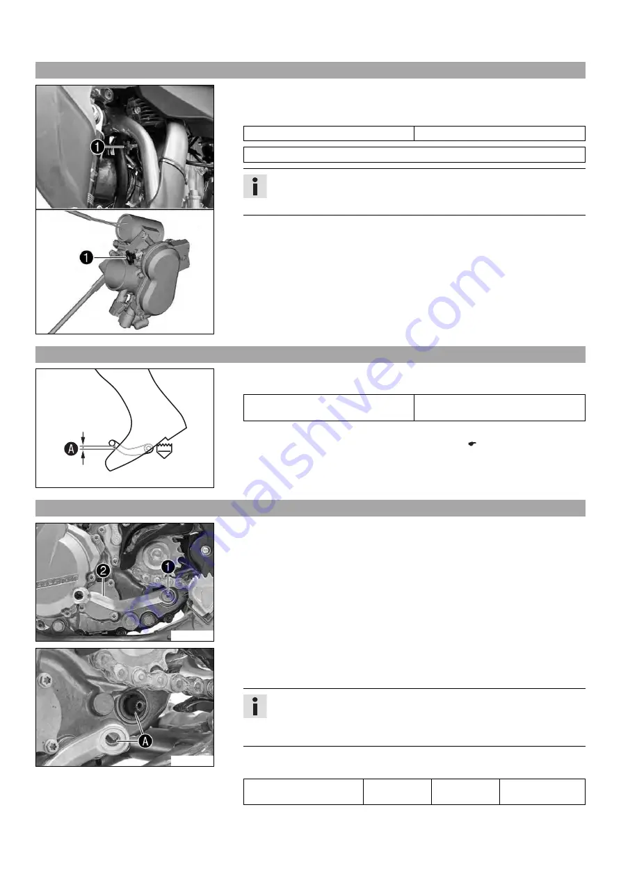
Run the engine until warm.

Set the desired idle speed by turning the idle speed adjusting screw

1

.

Guideline

Idle speed

2,250… 2,350 rpm

Tachometer (45129075000)

Info

Turn counterclockwise to decrease the idle speed.
Turn clockwise to increase the idle speed.

16.4

Checking the basic position of the shift lever

400692-10

Sit on the vehicle in the riding position and determine the distance

A

between the

upper edge of your boot and the shift lever.

Distance between shift lever and upper
edge of boot

10… 20 mm (0.39… 0.79 in)

» If the distance does not meet specifications:

Adjust the basic position of the shift lever.

x

(

p. 72)

16.5

Adjusting the basic position of the shift lever

x

L01309-10

Remove screw

1

and take off shift lever

2

.

L01310-10

Clean gear teeth

A

of the shift lever and shift shaft.

Mount the shift lever on the shift shaft in the required position and engage the
gearing.

Info

The range of adjustment is limited.
The shift lever must not come into contact with any other vehicle compo-
nents during the shift procedure.

Mount and tighten the screw.
Guideline

Screw, shift lever

M6

14 Nm
(10.3 lbf ft)

Loctite

®

243™

Summary of Contents for 450 SMR

Page 1: ...OWNER S MANUAL 2014 450 SMR Art no 3213039en ...

Page 2: ......

Page 3: ...ca tions prices colors forms materials services designs equipment etc without prior notice and without specifying reasons to adapt these to local conditions as well as to stop production of a particular model without prior notice KTM accepts no liability for delivery options deviations from illustrations and descriptions as well as misprints and other errors The models portrayed partly contain spe...

Page 4: ...nloaded 25 10 7 Checking static sag of shock absorber 25 10 8 Checking riding sag of shock absorber 25 10 9 Adjusting the spring preload of the shock absorber x 26 10 10 Adjusting the riding sag x 26 10 11 Checking the basic setting of the fork 27 10 12 Adjusting the compression damping of the fork 27 10 13 Adjusting the rebound damping of the fork 28 10 14 Handlebar position 28 10 15 Adjusting th...

Page 5: ...the spoke tension 63 14 ELECTRICAL SYSTEM 65 14 1 Removing the battery x 65 14 2 Installing the battery x 65 14 3 Charging the battery x 65 14 4 Changing the main fuse 66 15 COOLING SYSTEM 68 15 1 Cooling system 68 15 2 Checking the antifreeze and coolant level 68 15 3 Checking the coolant level 68 15 4 Draining the coolant x 69 15 5 Refilling coolant x 70 16 TUNING THE ENGINE 71 16 1 Checking the...

Page 6: ...standing In the interest of your own safety have these jobs performed by an authorized KTM workshop There your motorcycle will be opti mally cared for by specially trained experts using the specialist tools required Indicates a page reference more information is provided on the specified page 1 2 Formats used The typographical formats used in this document are explained below Specific name Identif...

Page 7: ... that will lead to environmental damage if the appropriate measures are not taken 2 4 Tampering warning Tampering with the noise control system is prohibited Federal law prohibits the following acts or the causing thereof 1 The removal or rendering inoperative by any person other than for purposes of maintenance repair or replacement of any device or element of design incorporated into any new veh...

Page 8: ... is required The manufacturer instructions for use must be followed After disassembly clean the parts that are to be reused and check them for damage and wear Change damaged or worn parts After you complete the repair or service work check the operating safety of the vehicle 2 8 Environment If you use your motorcycle responsibly you can ensure that problems and conflicts do not occur To protect th...

Page 9: ...M PowerParts for your vehicle can be found on the KTM website International KTM Website http www ktm com 3 4 Service A prerequisite for perfect operation and prevention of premature wear is that the service care and tuning work on the engine and chassis is properly carried out as described in the Owner s Manual Incorrect adjustment and tuning of the engine and chassis can lead to damage and breaka...

Page 10: ...LE 8 4 1 View of vehicle front left example L01266 10 1 Hand brake lever p 11 2 Clutch lever p 11 3 Filler cap 4 Plug in stand p 14 5 Air filter box lid 6 Engine number p 10 7 Shift lever p 13 8 Cold start button p 13 ...

Page 11: ...0 1 Kill switch p 11 2 Electric starter button p 11 3 Fork compression adjustment 4 Fork rebound adjustment 5 Foot brake lever p 14 6 Level viewer engine oil 7 Shock absorber compression adjustment 8 Level viewer for brake fluid rear 9 Shock absorber rebound adjustment ...

Page 12: ...steering head 5 3 Engine number S00125 10 The engine number 1 is stamped on the left side of the engine under the engine sprocket 5 4 Fork part number L01265 10 The fork part number 1 is stamped on the inner side of the axle clamp 5 5 Shock absorber part number L01269 10 The shock absorber part number 1 is stamped on the top of the shock absorber above the adjusting ring on the engine side ...

Page 13: ...dlebar 6 4 Kill switch L01261 10 Kill switch 1 is fitted on the left side of the handlebar Possible states Kill switch in basic position In this position the ignition circuit is closed and the engine can be started Kill switch pressed In this position the ignition circuit is interrupted a run ning engine stops and a non running engine will not start 6 5 Electric starter button L01250 12 Electric s...

Page 14: ... health hazard Fuel must not come into contact with the skin eyes or clothing Do not breathe in the fuel vapors If contact occurs with the eyes rinse with water immediately and contact a physician Immediately clean contaminated areas on the skin with soap and water If fuel is swallowed contact a physician immediately Change clothing that is contaminated with fuel Store fuel properly in a suitable ...

Page 15: ...ay The cold start button is deactivated The cold start button is pushed in all the way 6 10 Idle speed adjusting screw L01268 10 The idle setting of the throttle valve body has a big influence on the starting behavior stable idling and the response to throttle opening This means that an engine with a correctly set idle speed is easier to start than if the idle is set wrongly The idle speed is adju...

Page 16: ...ot brake lever L01262 10 Foot brake lever 1 is located in front of the right footrest The foot brake lever is used to activate the rear brake 6 13 Plug in stand L01255 10 The holder for the plug in stand 1 is the left side of the wheel spindle The plug in stand is used to park the motorcycle Info Remove the plug in stand before starting on a trip ...

Page 17: ...ke lever when you are not braking Warning Danger of accidents Unstable riding behavior Do not exceed the maximum permissible weight and axle loads Warning Risk of misappropriation Usage by unauthorized persons Never leave the vehicle while the engine is running Secure the vehicle against use by unauthorized persons Info When using your motorcycle remember that others may feel disturbed by excessiv...

Page 18: ...ssible rear axle load 190 kg 419 lb Run in the engine p 16 7 2 Running in the engine During the running in phase do not exceed the specified engine speed and engine performance Guideline Maximum engine speed During the first operating hour 7 000 rpm Maximum engine performance During the first 3 operating hours 75 Avoid fully opening the throttle ...

Page 19: ... the air filter Check the settings of all controls and ensure that they can be operated smoothly Check all screws nuts and hose clamps regularly for tightness Check the fuel supply 8 2 Starting Danger Danger of poisoning Exhaust gases are toxic and inhaling them may result in unconsciousness and or death When running the engine always make sure there is sufficient ventilation and do not start or r...

Page 20: ... standing for a long time Guideline 1 min Avoid frequent and longer slipping of the clutch This heats the engine oil the engine and the cooling system Ride with a lower engine speed instead of with a high engine speed and a slipping clutch 8 5 Applying the brakes Warning Danger of accidents If you brake too hard the wheels can lock Adapt your braking to the traffic situation and the road condition...

Page 21: ...ing over 8 8 Refueling Danger Fire hazard Fuel is highly flammable Never refuel the vehicle near open flames or burning cigarettes and always switch off the engine first Be careful that no fuel is spilt especially on hot vehicle components Clean up spilt fuel immediately The fuel in the fuel tank expands when warm and may emerge if overfilled Follow the instructions on refueling Warning Danger of ...

Page 22: ...e Open the filler cap p 12 A A 401522 10 Fill the fuel tank with fuel up to measurement A Guideline Measurement of A 35 mm 1 38 in Total fuel tank capacity approx 7 5 l 1 98 US gal Super unleaded ROZ 95 RON 95 PON 91 p 91 Close the filler cap p 12 ...

Page 23: ...ar sprocket engine sprocket and chain guide p 48 Check the chain tension p 46 Grease all moving parts e g hand lever chain and check for smooth operation x Check correct the fluid level of the hydraulic clutch p 51 Check the brake fluid level of the front brake p 53 Check the free travel of the hand brake lever Check the steering head bearing play p 35 Check the valve clearance x Check the clutch ...

Page 24: ...head bearing x p 36 Service the shock absorber x Change the spark plug and spark plug connector x Change the piston x Check measure the cylinder x Check the cylinder head x Change the valves valve springs and valve spring seats x Check the camshaft and rocker arm x Change the connecting rod conrod bearing and crank pin x Change the shaft seal rings of the water pump x Check the transmission and sh...

Page 25: ...the rear wheel suspension and not to the vehicle speed The high speed setting for example has an effect on the landing after a jump the rear wheel suspension compresses more quickly The low speed setting for example has an effect when riding over long ground swells the rear wheel suspension compresses more slowly These two ranges can be adjusted separately although the transition between high spee...

Page 26: ...ber of turns corresponding to the shock absorber type Guideline Compression damping high speed Comfort 2 turns Standard 1 5 turns Sport 1 turn Info Turn clockwise to increase damping turn counterclockwise to reduce damp ing 10 5 Adjusting the rebound damping of the shock absorber Caution Danger of accidents Disassembly of pressurized parts can lead to injury The shock absorber is filled with high ...

Page 27: ... difference between measurements A and B Check the static sag Static sag 20 mm 0 79 in If the static sag is less or more than the specified value Adjust the spring preload of the shock absorber x p 26 10 8 Checking riding sag of shock absorber 400990 10 Measure distance A of rear wheel unloaded p 25 With another person holding the motorcycle the rider wearing full protective cloth ing sits on the ...

Page 28: ...e the overall spring length when not under tension Tighten the spring by turning adjusting ring 2 to measurement A Guideline Spring preload 19 mm 0 75 in Info Depending on the static sag and or the riding sag it may be necessary to increase or decrease the spring preload Tighten screw 1 Guideline Screw shock absorber adjusting ring M5 5 Nm 3 7 lbf ft Finishing work Install the shock absorber x p 3...

Page 29: ...n the rider s weight can be com pensated by the spring preload However if the fork is often overloaded hard end stop on compression harder springs must be fit to avoid damage to the fork and frame 10 12 Adjusting the compression damping of the fork Info The hydraulic compression damping determines the fork suspension behavior L01263 10 Turn adjusting screws 1 clockwise all the way Info Adjusting s...

Page 30: ...f A to each other Hole distance A 15 mm 0 59 in The holes on the handlebar support are placed at a distance of B from the center Hole distance B 3 5 mm 0 138 in The handlebar can be mounted in four different positions In this way the handlebar can be mounted in the position that is most comfortable for the rider 10 15 Adjusting the handlebar position x B00375 10 Remove the four screws 1 Remove the...

Page 31: ...10 TUNING THE CHASSIS 29 Position the handlebar clamps Fit and evenly tighten the four screws 1 Guideline Screw handlebar clamp M8 20 Nm 14 8 lbf ft ...

Page 32: ... stand Note Danger of damage The parked vehicle may roll away or fall over Always place the vehicle on a firm and even surface L01255 10 Remove the motorcycle from the lift stand Remove the lift stand To park the motorcycle insert plug in stand 1 into the left side of the wheel spin dle Info Remove the plug in stand before riding 11 3 Bleeding the fork legs Preparatory work Raise the motorcycle wi...

Page 33: ...rake discs free of oil and grease and clean them with brake cleaner when necessary Clean and oil the dust boots and inner fork tube of both fork legs Universal oil spray p 93 Press the dust boots back into their normal position Remove excess oil Finishing work Install the fork protector p 32 Remove the motorcycle from the lift stand p 30 11 5 Removing the fork legs x Preparatory work Raise the mot...

Page 34: ...osition the brake line and clamp Mount and tighten screws 4 Finishing work Install the front wheel x p 60 11 7 Removing the fork protector L01273 11 Remove screws 1 and take off the clamp Remove screws 2 on the left fork leg Take off the fork protector Remove screws on the right fork leg Take off the fork protector 11 8 Installing the fork protector L01273 10 Position the fork protector on the lef...

Page 35: ...covering them Do not bend the cables and lines L00118 10 Remove O ring 3 Remove protective ring 4 Take out the lower triple clamp with the steering stem Take out the upper steering head bearing 11 10 Installing the lower triple clamp x 0 0 1 1 0 0 2 2 0 0 3 3 800221 10 Main work Clean the bearing and sealing elements check for damage and grease High viscosity grease p 92 Insert the lower triple cl...

Page 36: ...rew bottom triple clamp M8 12 Nm 8 9 lbf ft L00121 10 Tighten screw 4 Guideline Screw top steering head M20x1 5 12 Nm 8 9 lbf ft L00121 11 Mount and tighten screw 7 Guideline Screw top steering stem M8 17 Nm 12 5 lbf ft Loctite 243 L01324 11 Using a plastic hammer tap lightly on the upper triple clamp to avoid strains Tighten screws 8 Guideline Screw top triple clamp M8 17 Nm 12 5 lbf ft L01271 12...

Page 37: ...avel No play should be noticeable in the steering head bearing If there is noticeable play present Adjust the play of the steering head bearing x p 35 Move the handlebar to and fro over the entire steering range The handlebar must be able to move easily over the entire steering range No resting locations should be noticeable If click positions are noticeable Adjust the play of the steering head be...

Page 38: ...number plate L01257 11 Remove screw 1 and take off the clamp Remove screw 2 Take off the start number plate 11 15 Installing the start number plate L01257 10 Position the start number plate Mount and tighten screw 1 Guideline Remaining screws chassis M6 10 Nm 7 4 lbf ft The holding lugs engage Position the brake line and clamp Mount and tighten screw 2 11 16 Removing the front fender L00123 10 Rem...

Page 39: ... holding lugs engage 11 18 Removing the shock absorber x Preparatory work Raise the motorcycle with the lift stand p 30 Remove the manifold x p 41 L01294 10 Main work Remove screw 1 Remove screw cap 2 L01293 10 Press angle lever 3 toward the rear Press linkage lever 4 downward L01274 10 Raise the swingarm L01277 10 Remove the cable binders of the frame protector Remove screw 5 Remove frame protect...

Page 40: ...ion the frame protector Info Pay attention to the holding lugs Mount and tighten screw 2 Guideline Screw frame protector M5 3 Nm 2 2 lbf ft Attach the frame protector with a cable binder L01274 11 Lower the swingarm L01294 11 Position the angle lever and linkage lever Mount and tighten screw cap 3 Guideline Nut linkage lever to angle lever M14x1 5 80 Nm 59 lbf ft Mount and tighten screw 4 Guidelin...

Page 41: ...sly it push forward Make sure that the seat is correctly locked in Mount and tighten the screw of the seat fixing Guideline Remaining screws chassis M6 10 Nm 7 4 lbf ft 11 22 Removing the air filter box lid L01282 10 Condition The air filter box lid is secured Remove screws 1 L01282 11 Pull off the air filter box lid in area A sideways and remove it toward the front 11 23 Installing the air filter...

Page 42: ...ke fluid etc should be disposed of as stipulated in applicable regulations Preparatory work Remove the air filter box lid p 39 L01283 10 Main work Detach air filter holder 1 at the bottom and swing it to one side Remove the air filter with the air filter support Remove the air filter from the air filter support 11 25 Installing the air filter x L00943 10 Main work Mount the clean air filter onto t...

Page 43: ... in special cleaning liquid and allow it to dry properly Air filter cleaner p 92 Info Only press the air filter to dry it never wring it out Oil the dry air filter with a high quality filter oil Oil for foam air filter p 93 Clean the air filter box Clean the intake flange and check it for damage and tightness Finishing work Install the air filter x p 40 Install the air filter box lid p 39 11 27 Se...

Page 44: ...ach springs 2 Spring hooks 50305017000 L01276 11 Tighten screw 1 Guideline Remaining screws chassis M8 25 Nm 18 4 lbf ft 11 30 Removing the main silencer Warning Danger of burns The exhaust system gets very hot when the vehicle is driven Allow the exhaust system to cool down Do not touch hot components L01284 10 Disconnect spring 1 Spring hooks 50305017000 Remove screws 2 and take off the main sil...

Page 45: ... 10 Main work Remove all screws from the main silencer Remove protection cap 1 and O ring 2 Remove outer tube 3 and O ring 4 Pull the glass fiber yarn filling 5 from the inner tube 6 Clean the parts that are to be reinstalled Mount the new glass fiber yarn filling 5 on the inner tube Slide the O ring 4 and the outer tube 3 over the glass fiber yarn filling Insert the O ring 2 and the protection ca...

Page 46: ...suitable canister and keep away from children Preparatory work Remove the seat p 39 C00166 10 Main work Unplug connector 1 of the fuel pump C00233 10 Thoroughly clean the plug in connection of the fuel line using compressed air Info Under no circumstances should dirt enter into the fuel line Dirt in the fuel line clogs the injection valve Disconnect the plug in connection of the fuel line Mount wa...

Page 47: ...tact a physician immediately Change clothing that is contaminated with fuel Main work Check the throttle cable routing p 50 C00168 11 Position the fuel tank and fit the two spoilers to the sides of the radiator bracket Make sure that no cables are trapped or damaged Mount the fuel tank breather Mount and tighten screw 1 with the rubber bushing Guideline Remaining screws chassis M6 10 Nm 7 4 lbf ft...

Page 48: ...d in applicable regulations Info The service life of the chain depends largely on its maintenance 400725 01 Clean the chain regularly and then treat with chain spray Chain cleaner p 92 Off road chain spray p 92 11 37 Checking the chain tension Warning Danger of accidents Danger caused by incorrect chain tension If the chain is too taut the components of the secondary power transmission chain engin...

Page 49: ... in extreme cases If the chain is too loose however it may fall off the engine sprocket or rear sprocket and block the rear wheel or damage the engine Ensure that the chain tension is correct and adjust it if necessary Preparatory work Raise the motorcycle with the lift stand p 30 Check the chain tension p 46 L00139 10 Main work Loosen nut 1 Loosen nuts 2 Adjust the chain tension by turning adjust...

Page 50: ...hain links in the lower chain section Info Chain wear is not always even so you should repeat this measurement at different chain positions Maximum distance B at the longest chain section 272 mm 10 71 in If the distance B is greater than the specified measurement Change the power set x Info When the chain is replaced the rear sprocket and engine sprocket should also be changed New chains wear out ...

Page 51: ...isible on the front of the chain guide If the light part of the chain guide is worn Change the chain guide x L01258 01 Check that the chain guide is firmly seated If the chain guide is loose Tighten the chain guide Guideline Remaining screws chassis M6 10 Nm 7 4 lbf ft Finishing work Remove the motorcycle from the lift stand p 30 11 40 Checking the frame x 401519 01 Check the frame for cracking an...

Page 52: ...he handlebars and above the fuel tank bracket If the throttle cable is not routed as specified Correct the throttle cable routing Finishing work Install the fuel tank x p 45 Mount the seat p 39 11 43 Checking the rubber grip 401197 01 Check the rubber grips on the handlebar for damage and wear and to ensure they are firmly seated If a rubber grip is damaged worn or loose Change and secure the rubb...

Page 53: ...ounted on the handlebar to a horizontal position Remove screws 1 Remove cover 2 with membrane 3 Check the fluid level Fluid level below container rim 4 mm 0 16 in If the fluid level does not meet specifications Correct the fluid level of the hydraulic clutch Brake fluid DOT 4 DOT 5 1 p 90 Position the cover with the membrane Mount and tighten the screws 11 47 Changing the hydraulic clutch fluid x ...

Page 54: ...without bubbles To prevent overflow drain fluid occasionally from the master cylinder reservoir Remove the bleeding syringe Mount and tighten screws bleeder screw Correct the fluid level of the hydraulic clutch Guideline Fluid level below container rim 4 mm 0 16 in Position the cover with the membrane Mount and tighten the screws ...

Page 55: ...uces the thickness of the brake disc around the area used by the brake linings Brake discs wear limit Front 4 25 mm 0 1673 in Rear 3 5 mm 0 138 in If the brake disc thickness is less than the specified value Change the brake disc Check the front and rear brake discs for damage cracking and deformation If the brake disc shows signs of damage cracking or deformation Change the brake disc 12 3 Checki...

Page 56: ...stipulated in applicable regulations Info Never use DOT 5 brake fluid It is silicone based and purple in color Oil seals and brake lines are not designed for DOT 5 brake fluid Avoid contact between brake fluid and painted parts Brake fluid attacks paint Use only clean brake fluid from a sealed container Preparatory work Check the front brake linings p 54 L01289 10 Main work Move the brake fluid re...

Page 57: ... KTM workshop will be glad to help Warning Environmental hazard Hazardous substances cause environmental damage Oil grease filters fuel cleaners brake fluid etc should be disposed of as stipulated in applicable regulations Info Never use DOT 5 brake fluid It is silicone based and purple in color Oil seals and brake lines are not designed for DOT 5 brake fluid Avoid contact between brake fluid and ...

Page 58: ...ording to specifications L01295 10 Disconnect spring 1 Move the foot brake lever back and forth between the end stop and the contact to the foot brake cylinder piston and check free travel A Guideline Free travel at foot brake lever 3 5 mm 0 12 0 2 in If the free travel does not meet specifications Adjust the basic position of the foot brake lever x p 56 Reconnect spring 1 12 8 Adjusting the basic...

Page 59: ...he brake fluid level drops below marking A Add rear brake fluid x p 57 12 10 Adding rear brake fluid x Warning Danger of accidents Brake system failure If the brake fluid level drops below the specified marking or the specified value this is an indication that the brake system is leaking or that the brake linings are completely worn down Check the brake system and do not continue riding Your autho...

Page 60: ... in If the minimum thickness is less than specified Change the rear brake linings x p 58 Check the brake linings for damage and cracking If damage or cracking is visible Change the rear brake linings x p 58 12 12 Changing the rear brake linings x Warning Danger of accident Brake system failure Maintenance work and repairs must be carried out professionally Your authorized KTM workshop will be glad...

Page 61: ...ake caliper against the spokes Remove cotter pins 3 pull out pin 4 and remove the brake linings Clean the brake caliper and brake caliper support 100407 10 Check that leaf spring 5 in the brake caliper and sliding plate 6 in the brake caliper support are seated correctly Info The arrow on the leaf spring points in the rotation direction of the brake disc L00155 10 Insert the brake linings insert p...

Page 62: ...l out of the fork Info Always lay the wheel down in such a way that the brake disc is not dam aged L01301 10 Remove spacers 5 13 2 Installing the front wheel x Warning Danger of accidents Reduced braking efficiency due to oil or grease on the brake discs Always keep the brake discs free of oil and grease and clean them with brake cleaner when necessary L01301 11 Check the wheel bearing for damage ...

Page 63: ... several times The fork legs become aligned Tighten screws 5 Guideline Screw fork stub M8 15 Nm 11 1 lbf ft 13 3 Removing the rear wheel x Preparatory work Raise the motorcycle with the lift stand p 30 L01303 10 Main work Press the brake caliper by hand on to the brake disc in order to press back the brake piston Info Make sure when pushing back the brake piston that you do not press the brake cal...

Page 64: ...rs L01302 10 Lift the rear wheel into the swing arm position it and attach the chain Insert wheel spindle 2 L00139 11 Position chain adjuster 3 Mount nut 4 but do not tighten it yet Make sure that chain adjusters 3 are fitted correctly on adjusting screws 5 Check the chain tension p 46 Tighten nut 4 Guideline Nut rear wheel spindle M25x1 5 80 Nm 59 lbf ft Info The wide adjustment range of the chai...

Page 65: ...regardless of the actual state of wear If the tire is older than five years Change the tire 13 6 Checking the tire air pressure Info If the tire air pressure is too low this will lead to abnormal wear and overheating of the tire Correct tire air pressure ensures optimal riding comfort and the maximum service life of the tire 400695 01 Remove the protection cap Check the tire air pressure on cold o...

Page 66: ...ne frequencies from different spokes of equal length and diameter this is an indication of different spoke tensions You should hear a high note If the spoke tension varies Correct the spoke tension x Check the spoke torque Guideline Spoke nipple front wheel M4 5 5 6 Nm 3 7 4 4 lbf ft Spoke nipple rear wheel M4 5 5 6 Nm 3 7 4 4 lbf ft Torque wrench with various accessories in set 58429094000 ...

Page 67: ...at the bottom Lift the battery up and out 14 2 Installing the battery x C00246 10 Main work Insert the battery into the battery compartment with the terminals facing to the front Reconnect rubber band 1 Connect positive cable 2 and negative cable 3 Guideline Screw battery terminal M5 2 5 Nm 1 84 lbf ft Info Contact disks A must be mounted between screws 4 and cable sockets 5 with the claws facing ...

Page 68: ... battery is maintenance free which means that the acid level does not need to be checked Preparatory work Switch off all power consumers and switch off the engine Remove the seat p 39 Disconnect the negative cable of the battery to avoid damage to the onboard elec tronics 400240 10 Main work Connect the battery charger to the battery Switch on the battery charger Battery charger 58429074000 You ca...

Page 69: ...se wire A A reserve fuse 6 is located in the starter relay Install a new main fuse Fuse 58011109110 p 87 Check that the electrical equipment is functioning properly Tip Insert the spare fuse so that it is available if needed Mount the protection caps Mount the starter relay onto the holder and lay the cable Position the rear fairing Mount and tighten the screw Guideline Remaining screws chassis M6...

Page 70: ...nge clothing that is contaminated with coolant Keep coolant out of reach of children Condition The engine is cold 400243 10 Stand the motorcycle upright on a horizontal surface Remove the radiator cap Check antifreeze of coolant 25 45 C 13 49 F If the antifreeze of the coolant does not meet specifications Correct the antifreeze of the coolant Check the coolant level in the radiator Coolant level A...

Page 71: ... Allow the engine and cooling system to cool down In case of scalding rinse immediately with lukewarm water Warning Danger of poisoning Coolant is poisonous and a health hazard Coolant must not come into contact with the skin eyes or clothing If contact occurs with the eyes rinse with water imme diately and contact a physician Immediately clean contaminated areas on the skin with soap and water If...

Page 72: ...e skin with soap and water If coolant is swal lowed contact a physician immediately Change clothing that is contaminated with coolant Keep coolant out of reach of children L01306 10 Make sure that screw 1 is tightened Position the motorcycle upright Pour coolant in up to measurement A above the radiator fins Guideline Dimension A over the radiator fins 10 mm 0 39 in Coolant 1 20 l 1 27 qt Coolant ...

Page 73: ...e the handlebar to and fro over the entire steering range The idle speed must not change If the idle speed changes Adjust the play in the throttle cable x p 71 16 2 Adjusting the play in the throttle cable x Preparatory work Remove the seat p 39 Remove the fuel tank x p 43 Check the throttle cable routing p 50 S00140 10 Main work Move the handlebar to the straight ahead position Push back sleeves ...

Page 74: ...ot and the shift lever Distance between shift lever and upper edge of boot 10 20 mm 0 39 0 79 in If the distance does not meet specifications Adjust the basic position of the shift lever x p 72 16 5 Adjusting the basic position of the shift lever x L01309 10 Remove screw 1 and take off shift lever 2 L01310 10 Clean gear teeth A of the shift lever and shift shaft Mount the shift lever on the shift ...

Page 75: ...ion presses the two parts of the inner clutch hub against each other corresponding to the helical gearing thereby pressing the clutch facings against each other in addition to the clutch springs This additional press force means that the clutch springs require less preloading as a result when downshifting slippage arises briefly at the clutch and prevents rear wheel hopping 16 7 Adjusting the anti...

Page 76: ...and add or remove the desired washers Guideline Screw clutch spring retainer M5 8 Nm 5 9 lbf ft Info The spring preload must be the same on all screws L01311 10 Position the outer clutch cover Mount and tighten screws 1 Guideline Screw clutch cover M6 10 Nm 7 4 lbf ft ...

Page 77: ...5 10 Thoroughly clean plug in connection 1 of the fuel line using compressed air Info Under no circumstances should dirt enter into the fuel line Dirt in the fuel line clogs the injection valve Disconnect the plug in connection of the fuel line Pull fuel screen 2 out of the connecting piece Push the new fuel screen all the way into the connecting piece Lubricate the O ring and connect plug in conn...

Page 78: ... stipulated in applicable regulations Info Drain the engine oil only when the engine is warm Preparatory work Park the motorcycle on a level surface L01315 10 Main work Place a suitable container under the engine Remove oil drain plug 1 with the magnet and seal ring L01318 10 Remove screw plug 2 with the short oil screen and the O rings Info Do not remove screw A L01317 10 Remove screw plug 3 with...

Page 79: ...l filter 6 out of the oil filter housing Circlip pliers reverse 51012011000 Completely drain the engine oil Thoroughly clean the parts and sealing surface L01321 10 Lay the motorcycle on its side and fill the oil filter housing to about full with engine oil Insert the oil filter into the oil filter housing Lubricate the O ring of the oil filter cover and mount it with the oil filter cover 7 Mount ...

Page 80: ...emature wear to the engine L01313 10 Remove the oil filler plug 1 with the O ring from the clutch cover Add the same engine oil that was used when the motor was changed Engine oil SAE 10W 50 p 90 Info For optimal performance of the engine oil do not mix different types of engine oil If appropriate change the engine oil Install and tighten the oil filler plug with O ring Danger Danger of poisoning ...

Page 81: ... a normal motorcycle cleaner and then clean with a paintbrush Motorcycle cleaner p 92 Info Use warm water containing normal motorcycle cleaner and a soft sponge Never apply motorcycle cleaner to the dry vehicle always rinse with water first After rinsing the motorcycle with a gentle spray of water allow it to dry thoroughly Remove the plug from the exhaust system Warning Danger of accidents Reduce...

Page 82: ...e motorcycle out of service add fuel additive Fuel additive p 92 Refuel p 19 Clean the motorcycle p 79 Change the engine oil and oil filter and clean the oil screens x p 76 Check the antifreeze and coolant level p 68 Check the tire air pressure p 63 Remove the battery x p 65 Charge the battery x p 65 Guideline Storage temperature of battery without direct sunlight 0 35 C 32 95 F Store the vehicle ...

Page 83: ...ange the fuel filter x Defect in fuel injection system Read out the fault memory using the KTM diag nostics tool x Exhaust system leaky deformed or too little glass fiber yarn filling in main silencer Check exhaust system for damage Change the glass fiber yarn filling of the main silencer x p 43 Valve clearance too little Adjust the valve clearance x Engine dies during the trip Lack of fuel Refuel...

Page 84: ...20 TROUBLESHOOTING 82 Faults Possible cause Action Battery is discharged Unwanted power consumer Check the quiescent current x ...

Page 85: ...oo low Engine coolant temperature sensor input signal too high Blink code FI warning lamp MIL 13 FI warning lamp MIL flashes 1x long 3x short Error level condition Intake air temperature sensor input signal to low Intake air temperature sensor input signal too high Blink code FI warning lamp MIL 15 FI warning lamp MIL flashes 1x long 5x short Error level condition Rollover sensor A D type input si...

Page 86: ...16 32 2nd gear 18 30 3rd gear 20 28 4th gear 22 26 5th gear 24 24 Alternator 12 V 75 W Ignition Contactless controlled fully electronic ignition with digital igni tion adjustment Spark plug NGK LKAR8AI 9 Spark plug electrode gap 0 9 mm 0 035 in Cooling Water cooling permanent circulation of coolant by water pump Starting aid Electric starter 22 2 Engine tightening torques Screw cable holder in alt...

Page 87: ... water pump cover M6 10 Nm 7 4 lbf ft Oil jet for balancer shaft lubrication M6x0 75 4 Nm 3 lbf ft Oil nozzle for conrod bearing lubrica tion M6x0 75 4 Nm 3 lbf ft Plug oil channel M7 9 Nm 6 6 lbf ft Loctite 243 Screw rocker arm bearing M7 15 Nm 11 1 lbf ft Plug timing chain tensioner M8 8 Nm 5 9 lbf ft Screw plug crankshaft location M8 10 Nm 7 4 lbf ft Plug oil channel M10 15 Nm 11 1 lbf ft Locti...

Page 88: ...ing brake disc Rear Single disc brake with single piston floating caliper fixed brake disc Brake discs diameter Front 310 mm 12 2 in Rear 220 mm 8 66 in Brake discs wear limit Front 4 25 mm 0 1673 in Rear 3 5 mm 0 138 in Tire air pressure cold Front 10 30 C 50 86 F 1 9 bar 28 psi Rear 10 30 C 50 86 F 1 7 bar 25 psi Tire air pressure warm Front 75 85 C 167 185 F 2 1 bar 30 psi Rear 75 85 C 167 185 ...

Page 89: ...clicks Standard 12 clicks Sport 10 clicks Spring length with preload spacer s 482 mm 18 98 in Spring rate Weight of rider 65 75 kg 143 165 lb 4 6 N mm 26 3 lb in Weight of rider 75 85 kg 165 187 lb 4 8 N mm 27 4 lb in Gas pressure 1 2 bar 17 psi Fork length 920 mm 36 22 in Oil capacity per cartridge 195 ml 6 59 fl oz Fork oil SAE 4 48601166S1 p 90 Oil capacity fork leg without cartridge 380 ml 12 ...

Page 90: ...ctite 243 Screw front brake disc M6 14 Nm 10 3 lbf ft Loctite 243 Screw rear brake disc M6 14 Nm 10 3 lbf ft Loctite 243 Screw throttle grip M6 5 Nm 3 7 lbf ft Fuel connection on fuel tank M8 10 Nm 7 4 lbf ft Nut foot brake lever stop M8 20 Nm 14 8 lbf ft Nut rear sprocket screw M8 35 Nm 25 8 lbf ft Loctite 2701 Nut rim lock M8 12 Nm 8 9 lbf ft Remaining nuts chassis M8 25 Nm 18 4 lbf ft Remaining...

Page 91: ... ft Nut linkage lever to angle lever M14x1 5 80 Nm 59 lbf ft Nut swingarm pivot M16x1 5 100 Nm 73 8 lbf ft Screw top steering head M20x1 5 12 Nm 8 9 lbf ft Screw in nozzles cooling system M20x1 5 12 Nm 8 9 lbf ft Loctite 243 Screw front wheel spindle M24x1 5 45 Nm 33 2 lbf ft Nut rear wheel spindle M25x1 5 80 Nm 59 lbf ft ...

Page 92: ...illed water Coolant mixed ready to use Antifreeze 40 C 40 F Supplier Motorex COOLANT G48 Engine oil SAE 10W 50 According to JASO T903 MA p 94 SAE p 94 SAE 10W 50 Guideline Use only engine oils that comply with the specified standards see specifications on the container and that possess the corre sponding properties KTM recommends Motorex products Synthetic engine oil Supplier Motorex Cross Power 4...

Page 93: ... 95 RON 95 PON 91 Guideline Only use unleaded super fuel that matches or is equivalent to the specified fuel grade Fuel with an ethanol content of up to 10 E10 fuel is safe to use Info Do not use fuel containing methanol e g M15 M85 M100 or more than 10 ethanol e g E15 E25 E85 E100 ...

Page 94: ...ds Motorex products Supplier Motorex Protect Shine Fuel additive Guideline KTM recommends Motorex products Supplier Motorex Fuel Stabilizer High viscosity grease Guideline KTM recommends SKF products Supplier SKF LGHB 2 Long life grease Guideline KTM recommends Motorex products Supplier Motorex Bike Grease 2000 Motorcycle cleaner Guideline KTM recommends Motorex products Supplier Motorex Moto Clea...

Page 95: ... Paint cleaner and polish for high gloss and matte finishes bare metal and plastic surfaces Guideline KTM recommends Motorex products Supplier Motorex Clean Polish Rubber grip adhesive 00062030051 Supplier KTM Sportmotorcycle AG GRIP GLUE Universal oil spray Guideline KTM recommends Motorex products Supplier Motorex Joker 440 Synthetic ...

Page 96: ...rvice intervals are demanded for automobile engines high performance at high engine speeds are in the fore ground for motorcycle engines In most motorcycles the gearbox and the clutch are lubricated with the same oil as the engine The JASO MA Standard meets these special requirements SAE The SAE viscosity classes were defined by the Society of Automotive Engineers and are used for classifying oils...

Page 97: ... Chassis number 10 Clutch 73 adjusting 73 checking correcting the fluid level 51 fluid changing 51 Clutch lever 11 basic position adjusting 51 Cold start button 13 Compression damping fork adjusting 27 Compression damping high speed shock absorber adjusting 24 Compression damping low speed shock absorber adjusting 23 Coolant draining 69 refilling 70 Coolant level checking 68 Cooling system 68 Cust...

Page 98: ...Preparing for use advice on first use 15 after storage 80 checks and maintenance work when preparing for use 17 Protective clothing 6 R Rear sprocket checking 48 Rear wheel installing 62 removing 61 Rebound damping fork adjusting 28 shock absorber adjusting 24 Refueling fuel 19 Riding sag adjusting 26 Rubber grip checking 50 securing 50 S Safe operation 5 Seat mounting 39 removing 39 Service 7 Ser...

Page 99: ...ghtening torques 84 fork 87 shock absorber 87 tires 87 Throttle cable play checking 71 Throttle cable routing checking 50 Throttle grip 11 Tire air pressure checking 63 Tire condition checking 63 Transport 19 Troubleshooting 81 82 Type label 10 U Use definition 5 V View of vehicle front left side 8 rear right side 9 W Warranty 7 Work rules 6 ...

Page 100: ... 3213039en 3213039en 06 2013 KTM Sportmotorcycle AG 5230 Mattighofen Austria http www ktm com Photo Mitterbauer KTM ...

Reviews: