KTR-STOP
®
M-A-F B-xx
Operating/Assembly instructions
KTR-N
Sheet:
Edition:
445145 EN
12 of 23
1
Please observe protection
note ISO 16016.
Drawn:
2022-12-20 Ka/Wie
Replacing:
Verified:
2022-12-21 Ka
Replaced by:
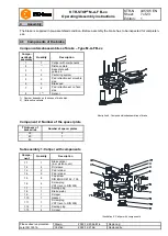
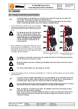
In order to avoid any contact between the brake disk and the brake resulting from thermal
expansion, the distance of the brake as per table 3 needs to be observed.
!
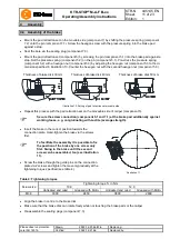
Make sure that the tolerances of the brake disk do not exceed the figures specified in illust-
ration 3.
•
Optional component:
Assemble the sensor (component 8) according to chapter 6.2.
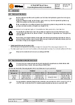
The centering systems need to be reset with initial assembly or after having replaced brake
pads or single parts, respectively. This is the only way to ensure that the gap between the
brake disk and the brake pad on the bottom side is set to the right value and the pad does
not touch on any side.
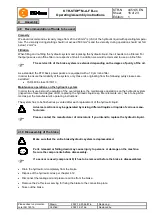
The centering systems need to be regularly reset with wear of the brake pads. For that pur-
pose repeat the complete chapter Setting/resetting of the centering system.
•
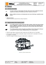
Measure the gap between the brake disk and the brake pad on the bottom side via a feeler gauge.
•
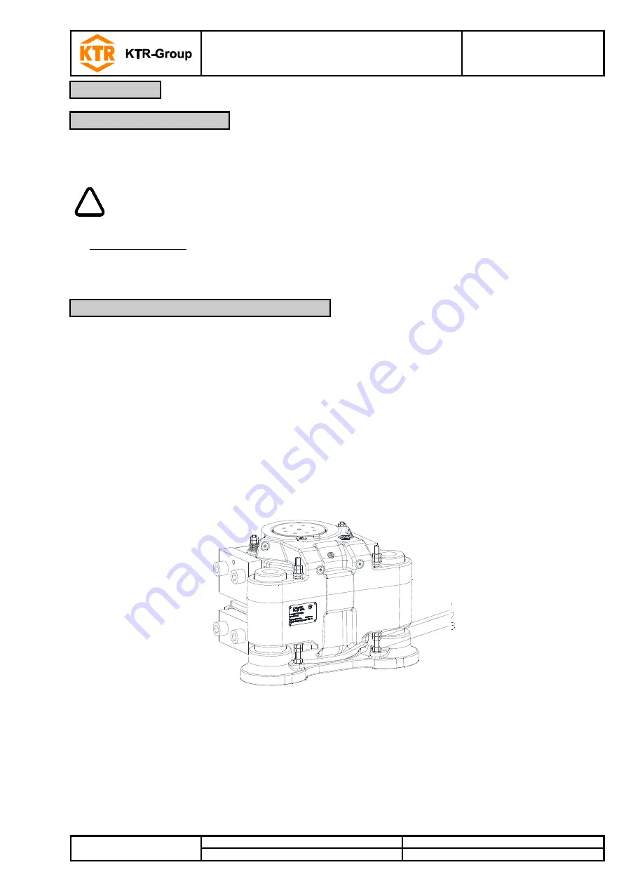
Set the gap to the value specified by screwing the hexagon nut marked with 1 in illustration 12 in the direc-
tion upwards or downwards.
•
Counter the hexagon nut with the hexagon nut marked with 2 in illustration 12.
Illustration 12: Setting of centering system
4
Assembly
4.4 Assembly of the brake
4.5 Setting/resetting of the centering system


