KTR-STOP
®
M-A-F B-xx
Operating/Assembly instructions
KTR-N
Sheet:
Edition:
445145 EN
21 of 23
1
Please observe protection
note ISO 16016.
Drawn:
2022-12-20 Ka/Wie
Replacing:
Verified:
2022-12-21 Ka
Replaced by:
•
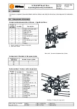
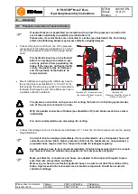
Fit the pre-assembled unit carefully on the guide pins.
Make sure that the centering system (component 4) is not damaged.
•
Screw the bolt (component 4.1) into the base plate (component 3.1).
•
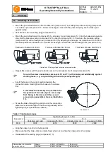
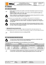
Measure the gap between the brake disk and the brake pad on the bottom side via a feeler gauge.
•
Set the gap to the value specified by screwing the hexagon nut marked with 1 in illustration 21 in the direc-
tion upwards or downwards.
•
Counter the hexagon nut with the hexagon nut marked with 2 in illustration 21.
•
Repeat chapters 4.2 to 4.8.
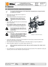
Illustration 21: Setting of centering system
KTR-STOP
®
M-A-F B-xx
is a low-maintenance brake. We recommend to perform a visual inspection and an ope-
rational testing on the brake
at least once a year
. Here you should put special emphasis on leakages, corrosion,
wear of brake pads and the condition of the screw connections.
If you realize any irregularities, perform repairs accordingly.
5
Maintenance
5.2 Maintenance of the brake / replacement of single parts
5.3 Maintenance and service

