background image


KTR-STOP

® 

YAW M B-xx 

Operating/Assembly instructions


KTR-N 
Sheet: 
Edition: 

445120 EN 
9 of 16 


Please observe protection 

note ISO 16016. 

Drawn: 

2019-11-18 Shg/Wie 

Replacing: 

--- 

Verified: 

2019-11-22 Shg 

Replaced by: 


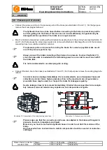
  Connect the pressure oil line to the pressure ports of the brake (see illustration 10 and 11). For that purpose 

remove the screw plug beforehand. 


The hydraulic lines have to be rinsed before connecting to the brake to prevent any partic-
les from getting into the brake. If the lines are not rinsed sufficiently, the gaskets may be 
damaged and the operation of the brake is no longer ensured.


  Mount a miniature measuring coupling with a miniature measuring hose to the venting hole (see illustration 10 

and 11), for that purpose the screw plug needs to be removed beforehand. Discharge the end of the miniature 
measuring hose in a suitable collection container. 


The pressure ports on top serve for venting the brake. For a wash-up system make use of 
one of the pressure ports on top. 


Always connect the brake consisting of two halves to a pressure line (see illustration 11), 
since the brake disk is loaded with the full braking power on one side in case if one half of 
the brake fails. 


It is not recommended to use steel plugs for venting. 


  Connect the drain line to the brake (see illustration 10 and 11). For that purpose remove the sealing plug befo-

rehand. 


In order to locate a leakage immediately, it is recommended to use a transparent hose and 
collection container. Since higher pressures (5 bar at the maximum) are not generated, a 
pneumatic hose may be used, too. Inspect the brake for leakages regularly. 


Severe leakages have to be removed immediately. Oil which has escaped has to be comple-
tely removed, since oil remains may vaporize on hot components and ignite. 


Illustration 10: Connections of the drain lines/pressure lines 

Illustration 11: Pressure port of a brake 


Please make sure that the connections and hoses are adapted to the brakes with regard to 
pressure, flow rate, temperature and liquid. 
Moreover, you have to use flexible hydraulic hoses in order to not limit the motions of the 
brake. 
Any hoses which are located close to mobile components should be secured or coated ac-
cordingly. 


Assembly 

4.5  Pressure port of a brake 
Summary of Contents for KTR-STOP YAW M B Series

Page 1: ...observe protection note ISO 16016 Drawn 2019 11 18 Shg Wie Replacing Verified 2019 11 22 Shg Replaced by YAW M YAW M B xx is a disk brake in an active design serving for transmitting a brake force on...

Page 2: ...warnings 5 2 4 Intended use 5 3 Storage transport and packaging 6 3 1 Storage 6 3 2 Transport and packaging 6 4 Assembly 6 4 1 Components of the brake 6 4 2 Preparation of assembly 7 4 3 Brake pads 7...

Page 3: ...ete brake cm2 254 Volume for each brake caliper with 1 mm stroke cm3 25 4 Pressure port G 1 4 Oil bleed G 1 4 Max clamping force kN 203 Max operating pressure bar 160 Thickness of brake disk mm 30 50...

Page 4: ...Replaced by Dimensions of brake disk Illustration 3 Internal assembly of brake Illustration 4 External assembly of brake Table 2 Calculation of brake disk Internal assembly of brake External assembly...

Page 5: ...wing safety indica tions All operations on and with the brake have to be performed taking into account safety first Make sure to switch off the power pack before you perform your work on the brake Sec...

Page 6: ...lamps or electrical high voltage appliances Humid storage rooms are not suitable Please make sure that condensation is not generated The best relative air humidity is less than 65 In order to avoid a...

Page 7: ...be removed by means of solvents The connection between connection plate and brake is defined as frictionally engaged Any residues of oil dirt and corrosion protection reduce the coefficient of fricti...

Page 8: ...Insert the O ring component 4 in the counterbore Depending on the thickness of brake disk Put the distance plate component 3 onto the housing and insert the second gasket component 4 into the indentat...

Page 9: ...ng of two halves to a pressure line see illustration 11 since the brake disk is loaded with the full braking power on one side in case if one half of the brake fails It is not recommended to use steel...

Page 10: ...ge the end of the minia ture measuring hose in a suitable collection container The pressure ports on top serve for venting the brake For a wash up system make use of one of the pressure ports on top A...

Page 11: ...insed with hydraulic oil Repeat this process until a stream of clean oil dissipates from the miniature measuring hose Remove the miniature measuring hose If the miniature measuring coupling is removed...

Page 12: ...mm s and the viscosity during operation should not fall below 12 mm s Filtration When filling and re filling the hydraulic system and replacing the hydraulic liquid the oil needs to be filtered For t...

Page 13: ...to 13 Remove the 8 off screws M27 serving for fixing the brake to the connection plate Take out the brake Depending on the thickness of brake disk Remove the distance plate after having taking out th...

Page 14: ...repa ration of assembly Repeat this chapter with the half of brake at the bottom Screw the brake to the connection plate by means of 8 off screws and tighten them hydraulically evenly gradually at 1 3...

Page 15: ...h a reassembly of the brake piston basically new gaskets and scrapers have to be used since their operativeness is no longer ensured due to wear and damages Grease the gaskets and scrapers with hydrau...

Page 16: ...wear of brake pads and the condition of the screw connections If you realize any irregularities perform repairs accordingly A basic requirement to ensure the readiness for use of the brake is a stock...

Reviews: