KTR-STOP
®
YAW M B-xx
Operating/Assembly instructions
KTR-N
Sheet:
Edition:
445120 EN
8 of 16
1
Please observe protection
note ISO 16016.
Drawn:
2019-11-18 Shg/Wie
Replacing:
---
Verified:
2019-11-22 Shg
Replaced by:
STOP
In order to avoid any injuries please always make use of proper lifting equipment.
On the reverse side of the brakes there are threads for eye bolts serving for using lifting devices. The eye bolts
should be disassembled after assembly of the brake and stored in a safe place.
!
In order to avoid any damages on the brake, never twist a rope or another lifting tool around
damageable components.
•
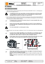
Before you start with the assembly each one dust protection
plug needs to be removed from both housings (component
1).
•
Insert the brake pads into the housing as deep as possible.
Compress the brake pads and brake pistons manually.
•
Please make sure that the connection surface is in parallel
with the brake and the tolerances as per illustration 5 are
observed.
Illustration 8: Dust protection plug
•
Push a housing in the correct position of the connection plate and fasten the housing via 2 cap screw M10.
•
Insert the O-ring (component 4) in the counterbore.
•
Depending on the thickness of brake disk:
Put the distance plate (component 3) onto the housing and insert the second gasket (component 4) into the
indentation of the distance plate.
•
Fit the second housing in the correct position onto the first
housing resp. distance plate.
•
Screw the brake to the connection plate by means of 8-off
screws and tighten them hydraulically evenly gradually at 1/3
and afterwards 2/3 of the tightening torque T
A
(see table 3).
Afterwards tighten the screws at the full tightening torques
specified in table 3 hydraulically. For any other tightening
procedures please consult with KTR.
Illustration 9: Tightening of connection screws
Preferably use the order specified in illustration
9.
Table 3: Tightening torques
Screw size
Tightening torque T
A
[Nm]
– 10.9
Untreated and oiled
Greased with MoS
2
M27
1496
1100
•
Align the brake in centre to the brake disk.
•
Make sure that the brake disk can rotate freely while not touching the housing.
In order to avoid any contact between the brake disk and the brake resulting from thermal
expansion, the distance of the brake as per table 2 needs to be observed.
!
Make sure that the tolerances of the brake disk do not exceed the figures specified in illust-
ration 5.
4
Assembly
4.4 Assembly of the brake

