RADEX
®
-N
Operating/Assembly instructions
KTR-N
Sheet:
Edition:
47110 EN
18 of 31
24
Please observe protection
note ISO 16016.
Drawn:
2019-07-23 Pz/Wb
Replacing:
KTR-N dated 2018-07-17
Verified:
2019-07-26 Pz
Replaced by:
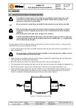
If used in potentially explosive atmospheres the setscrews to fasten the hubs as well as all
screw connections must be secured against working loose additionally, e. g. conglutinating
with Loctite (average strength).
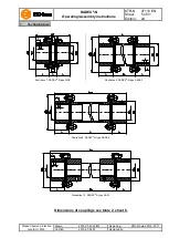
For vertical alignment of the coupling the distance dimension E (see table 1 and 2) is decisive. In order to set the
right dimension E you should proceed as follows:
•
Mount the flange hubs on the shaft of driving and driven side. Make sure that the flange hub with the disk for
vertical support is at the bottom (see illustration 24 and 25 as an alternative).
•
The internal sides of the flange hub on top or centering surface of the flange hub at the bottom must be flush
with the front sides of the shafts (see illustration 24 and 25 as an alternative).
•
Shift the power packs in axial direction until the distance dimension E is achieved (see table 1 or 2).
•
Fasten the flange hubs by tightening the setscrews DIN EN ISO 4029 with a cup point (tightening torque see
table 7).
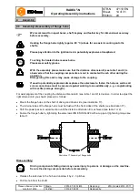
With the assembly of a spacer make sure that the flange hub with the disk for vertical
support is at the bottom.
Illustration 24: Vertical assembly (preferred assembly)
Illustration 25: Vertical assembly (as an alternative)
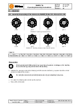
Disassembly:
STOP
Driving components falling down may cause injury to persons or damage on the machine.
Secure the driving components before disassembly.
•
Release the setscrew in the hub and unscrew it by 2 - 3 pitches.
•
Pull the hub from the shaft.
4
Assembly
4.6 Vertical assembly/disassembly


