RADEX
®
-N
Operating/Assembly instructions
KTR-N
Sheet:
Edition:
47110 EN
24 of 31
24
Please observe protection
note ISO 16016.
Drawn:
2019-07-23 Pz/Wb
Replacing:
KTR-N dated 2018-07-17
Verified:
2019-07-26 Pz
Replaced by:
!
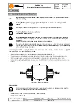
Before start-up make absolutely sure that the transport lock (see illustration 21) have been
removed.
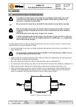
Before start-up of the coupling, inspect the tightening of the setscrews in the flange hubs, the alignment and the
distance dimension E and adjust, if necessary, and also inspect all screw connections for the tightening torques
specified.
If used in hazardous locations the setscrews to fasten the flange hubs as well as all screw
connections must be secured against working loose additionally, e. g. conglutinating with
Loctite (average strength).
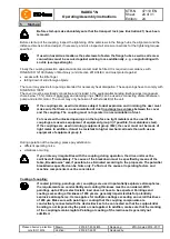
Finally the coupling protection against accidental contact must be fitted. It is required in accordance with
DIN EN ISO 12100 (Safety of Machinery) and directive 2014/34/EU and must protect against
•
access with the little finger
•
falling down of solid foreign objects.
The cover may provide for openings intended for necessary heat dissipation. These openings have to comply with
DIN EN ISO 13857.
The cover must be electrically conductive and included in the equipotential bonding. Bellhousings (magnesium
share below 7.5 %) made of aluminium and damping rings (NBR) can be used as connecting element between
pump and electric motor. The cover may only be taken off with standstill of the unit.
If the couplings are used in locations subject to dust explosion and in mining the user must
make sure that there is no accumulation of dust in a dangerous volume between the cover
and the coupling. The coupling must not operate in an accumulation of dust.
For covers with unlocked openings on the top face no light metals must be used if the
couplings are used as equipment of equipment group ll (if possible, from stainless steel).
If the couplings are used in mining (equipment group l M2), the cover must not be made of
light metal. In addition, it must be resistant to higher mechanical loads than with use as
equipment of equipment group ll.
During operation of the coupling, please pay attention to
•
different operating noise
•
vibrations occurring.
!
If you note any irregularities with the coupling during operation, the drive unit must be
switched off immediately. The cause of the breakdown must be specified by means of the
table „Breakdowns“ and, if possible, be eliminated according to the proposals. The potential
breakdowns specified can be hints only. To find out the cause all operating factors and
machine components must be considered.
Coating of coupling:
If coated (priming, paintings, etc.) couplings are used in potentially explosive atmospheres,
the requirements on conductibility and coating thickness must be considered. With
paintings up to 200 µm electrostatic load does not have to be expected. Paintings and
coatings exceeding a thickness of 200 µm are generally impermissible for potentially
explosive atmospheres. It also applies for multiple coatings exceeding an overall thickness
of 200 µm. Make sure with painting or coating that the coupling components are
conductively connected with the device/devices to be connected so that the equipotential
bonding is not impeded by the paint or coat applied. In addition, make sure that the marking
of the coupling remains legible. Painting or coating of the lamina set is generally not
admitted.
5
Start-up


