ROTEX
®
Operating/Assembly instructions
KTR-N
Sheet:
Edition:
40210 EN
14 of 22
22
Please observe protection
note ISO 16016.
Drawn:
2017-09-06 Pz/Bru
Replacing:
KTR-N dated 2017-01-02
Verified:
2017-09-06 Pz
Replaced by:
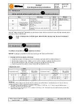
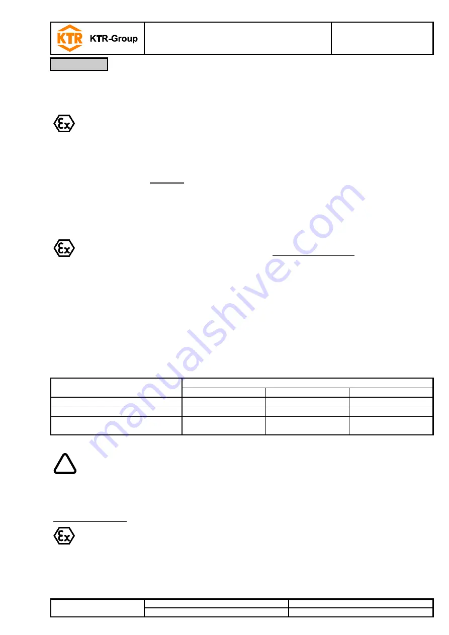
Before start-up of the coupling, please inspect the tightening of the setscrews in the hubs, the alignment and the
distance dimension E and adjust, if necessary, and also inspect all screw connections for the tightening torques
specified, dependent on the type of coupling.
If used in hazardous locations the setscrews to fasten the hubs as well as all screw
connections must be secured against working loose additionally, e. g. conglutinating with
Loctite (average strength).
Finally the coupling protection against accidental contact must be fitted.
The cover must be electrically conductive and included in the equipotential bonding. Bellhousings (magnesium
share below 7.5 %) made of aluminium and damping rings (NBR) can be used as connecting element between
pump and electric motor. The cover may only be taken off with standstill of the unit.
During operation of the coupling, please pay attention to
different operating noise
vibrations occurring.
If the couplings are used in locations subject to dust explosion and in mining the user must
make sure that there is no accumulation of dust in a dangerous volume between the cover
and the coupling. The coupling must not operate in an accumulation of dust.
For covers with unlocked openings on the top face no light metals must be used if the
couplings are used as equipment of equipment group ll (
if possible, from stainless steel
).
If the couplings are used in mining (equipment group l M2), the cover must not be made of
light metal. In addition, it must be resistant to higher mechanical loads than if it is used as
equipment of equipment group ll.
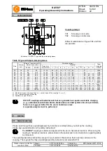
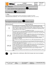
The minimum distan
ce „Sr“ between the protective device and the rotating parts must at least correspond to the
figures specified below.
If the protective device is used as cover, regular openings can be arranged from the point of view explosion
protection that must not exceed the following dimensions:
Openings
Cover [mm]
Top side
Lateral components
Distance „Sr“
Circular - max. diameter
4
8
10
Rectangular - max. lateral length
4
8
10
Straight or curved slot - max. lateral
length/height
not permissible
8
20
!
If you note any irregularities with the coupling during operation, the drive unit must be
switched off immediately. The cause of the breakdown must be specified by means of the
table „Breakdowns“ and, if possible, be eliminated according to the proposals. The potential
breakdowns mentioned can be hints only. To find out the cause all operating factors and
machine components must be considered.
Coating of coupling:
If coated (priming, paintings, etc.) couplings are used in hazardous locations, the requirements on
conductibility and coating thickness must be considered. In case of paintings up to 200 µm
electrostatic load does not have to be expected. Multiple coatings exceeding 200 µm are prohibited
for explosion group llC.
5
Start-up


