
ROTEX
®
Operating/Assembly instructions
KTR-N
Sheet:
Edition:
40210 EN
8 of 22
22
Please observe protection
note ISO 16016.
Drawn:
2017-09-06 Pz/Bru
Replacing:
KTR-N dated 2017-01-02
Verified:
2017-09-06 Pz
Replaced by:
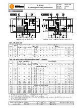
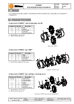
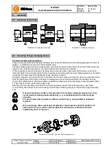
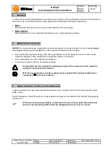
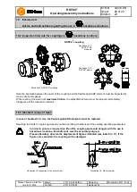
The coupling is generally supplied in individual parts. Before assembly the coupling has to be inspected for
completeness.
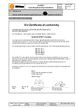
Components of ROTEX
®
, shaft coupling type No. 001
Component
Quantity
Description
Illustration 6: ROTEX
®
1
2
Hub
2
1
Spider
1)
3
5
2)
DZ elements
1)
4
2
Setscrews
DIN EN ISO 4029
1) Optionally spider or DZ elements
2) With size 180 the quantity is 6.
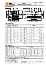
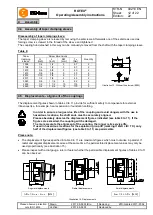
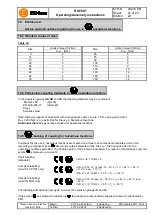
Components of ROTEX
®
, type DKM
1)
Component
Quantity
Description
Illustration 7: ROTEX
®
DKM
1
2
Hub
2
2
Spider
3
1
DKM spacer
4
2
Setscrews
DIN EN ISO 4029
1) Type DKM not available with DZ elements.
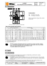
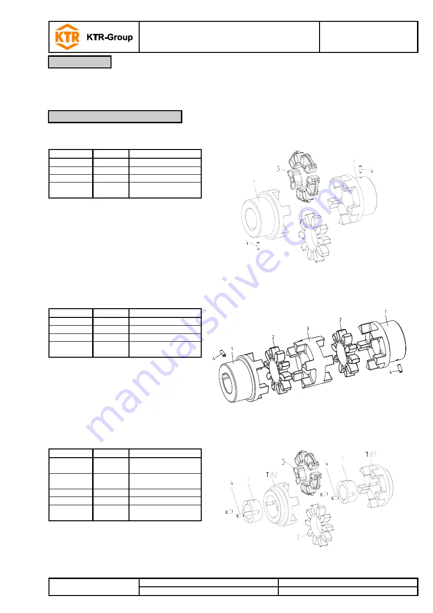
Components of ROTEX
®
, type with taper clamping sleeve
Component
Quantity
Description
Illustration 8: ROTEX
®
type with taper clamping sleeve
TB1/TB2
2
Hub for taper
clamping sleeve
1
2
Taper clamping
sleeve
2
1
Spider
1)
3
5
2)
DZ elements
1)
4
4
Setscrews
DIN EN ISO 4029
1) Optionally spider or DZ elements
2) With size 180 the quantity is 6.
4
Assembly
4.1 Components of the coupling


