ROTEX
®
Operating/Assembly instructions
KTR-N
Sheet:
Edition:
40210 EN
9 of 22
22
Please observe protection
note ISO 16016.
Drawn:
2017-09-06 Pz/Bru
Replacing:
KTR-N dated 2017-01-02
Verified:
2017-09-06 Pz
Replaced by:
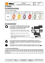
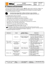
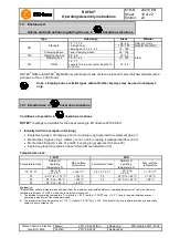
Features of standard spiders
Spider hardness
(Shore)
92 Shore A
95/98 Shore A
64 Shore D
T-PUR
®
(orange)
PUR
(yellow)
T-PUR
®
(purple)
PUR
(red)
T-PUR
®
(light green)
PUR
(natural white
1)
)
Marking
(colour)
1) Natural white with green marking of teeth
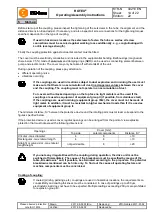
STOP
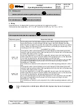
The maximum permissible bore diameters d (see table 1
to 5 in chapter 1 - technical data) must not be exceeded.
If these figures are disregarded, the coupling may tear.
Rotating particles may cause danger to life.
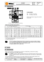
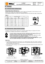
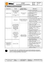
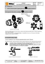
Hub bores machined by the customer have to observe
concentricity or axial runout, respectively (see illustration
9).
Please make absolutely sure to observe the figures for
Ø d
max
.
Carefully align the hubs when the finish bores are drilled.
Please provide for a setscrew according to
DIN EN ISO 4029 with a cup point or an end plate to fasten
the hubs axially.
Illustration 9: Concentricity and axial runout
!
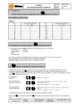
The customer bears the sole responsibility for all machining processes performed
subsequently on unbored or pilot bored as well as finish machined coupling components
and spare parts. KTR does not assume any warranty claims resulting from insufficient
remachining.
KTR supplies unbored or pilot bored coupling components and spare parts only upon
explicit request of the customer. These parts are additionally labelled with the symbol
.
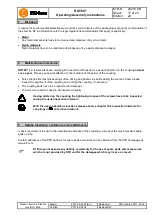
Table 6: Setscrews DIN EN ISO 4029
Size
14
19
24
28
38
42
48
55
65
75
90
100
110
125 140
160 180
Dimension G
M4
M5
M5
M8
M8
M8
M8
M10 M10 M10 M12 M12 M16 M16 M20 M20 M20
Dimension t
5
10
10
15
15
20
20
20
20
25
30
30
35
40
45
50
50
Tightening
torque T
A
[Nm]
1.5
2
2
10
10
10
10
17
17
17
40
40
80
80
140
140 140
4
Assembly
4.1 Components of the coupling
4.2 Advice for finish bore


