KTR Kupplungstechnik
GmbH
D-48407 Rheine
B o W e x - E L A S T I C
®
Operating-/Assembly Instructions
Design 065 (HEW1 and HEW2)
KTR-N
sheet:
edition:
40114 E
5
4
Gezeichnet:
08.04.04 Sha/Hk
Ersatz für:
KTR-N vom 01.12.99
Schutzvermerk
ISO 16016 beachten.
Geprüft:
08.04.04 Sha
Ersetzt durch:
4 Assembly
4.2 Hint regarding the finish bore
STOP
D A N G E R !
The maximum permissible bore diameters d (see table 1 in
chapter 1 - Technical Data) must not be exceeded. If these
figures are disregarded, the coupling may tear. Rotating
particles may cause serious danger.
•
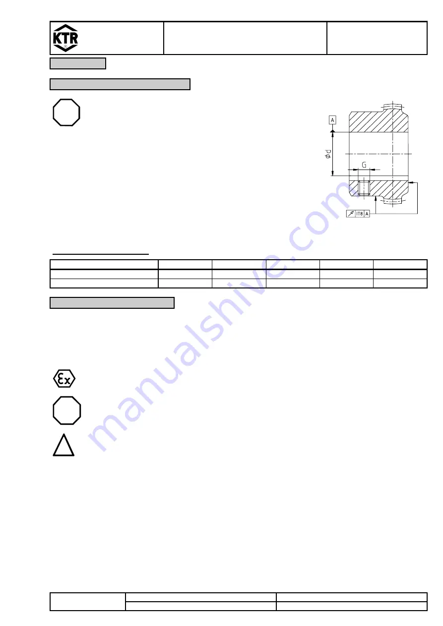
Hub-/coupling flange bores machined by the customer have to
observe concentric running or axial running, respectively (see
picture 5).
•
Please make absolutely sure to observe the figures for d
max
.
•
Carefully align the hub and the coupling flange when the finish
bores are brought in.
•
Please provide for a setscrew or an end plate for the axial
fastening of the hub and the coupling flange.
picture 5: concentric running
and axial running
Table 3: Setscrews DIN 916
BoWex-ELASTIC
®
size
42 HEW
48 HEW
65 HEW
80 HEW
G 80 HEW
screw size
M8
M8
M10
M10
M10
tightening torque T
A
[Nm]
10 10 17 17 17
4.3 Assembly of the Coupling
A T T E N T I O N !
We recommend to check bores, shaft, keyway and feather key for dimensional accuracy
before assembly.
Heating the hub and coupling flange slightly (approx. 80 °C) allows for an easier installation onto the shaft.
P R E C A U T I O N !
Please pay attention to the danger of ignition in hazardous areas.
STOP
D A N G E R !
Touching the heated parts causes burns.
We would recommend to wear safety gloves.
!
C A U T I O N !
For the assembly please make sure that the distance dimension E (see table 1) is kept to
ensure that the elastomer part can be moved axially.
Disregarding this hint may cause damage on the coupling.
•
Assemble the hub and the coupling flange onto the shafts.
•
Safe the coupling hub and the coupling flange by tightening the setscrews DIN 916 with cup point or by an end
disk.
•
Put the elastomer part in front of the flange hub.
•
First hand-screw the parts.
•
Use screws of the property class 8.8 or higher.
•
Tighten the screws with a suitable dynamometric key up to the tightening torques T
A
indicated in table 4.


