


KTR Kupplungstechnik
GmbH
D-48407 Rheine
B o W e x - E L A S T I C
®
Operating-/Assembly Instructions
Design 065 (HEW1 and HEW2)
KTR-N
sheet:
edition:
40114 E
6
4
Gezeichnet:
08.04.04 Sha/Hk
Ersatz für:
KTR-N vom 01.12.99
Schutzvermerk
ISO 16016 beachten.
Geprüft:
08.04.04 Sha
Ersetzt durch:
4 Assembly
4.3 Assembly of the Coupling
Continuation:
•
Safe the screwing with a suitable screw glue.
!
C A U T I O N !
Please observe the manufacturer´s instructions when using the glue.
Do not put any glue onto the rubber surfaces.
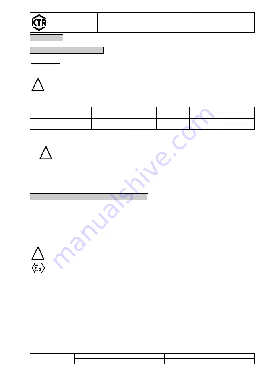
Table 4:
BoWex-ELASTIC
®
size
42 HEW
48 HEW
65 HEW
80 HEW
G 80 HEW
screw
size
M6 M6 M8 M10
M10
number
of
screws 6 8 8 8 8
tightening torque T
A
[Nm]
14 14 35 69 69
•
Displace the machine parts axially until the assembly dimension L
HEW1
or L
HEW2
is reached.
!
C A U T I O N !
For the assembly please make sure that the hub toothing is covered completely by the
internal toothing of the Elastomer part. (Please observe the assembly dimensions L
HEW1
and L
HEW2
.)
In case of non-observance, the coupling can be damaged.
•
If the position of the machine parts has already been indicated previously, the assembly dimension can be
adjusted by an axial displacement of the hub on the shaft.
4.4 Displacements - Alignment of the Couplings
The
BoWex-ELASTIC
®
HEW
couplings accept a deviation of position of the machine parts to be connected up to
the data indicated in table 5.
In case of the alignment, the radial and angular displacement should be as slight as possible, because the lifetime
is increased hereby under the same operating conditions.
The alignment of the
BoWex-ELASTIC
®
HEW
coupling has to be effected from the shaft-sided coupling hub to
one of the processed surfaces of the flange hub.
!
C A U T I O N !
In order to ensure a long lifetime of the coupling and to avoid dangers regarding the use in
hazardous areas, the shaft ends must be accurately aligned.
Please absolutely observe the displacement figures indicated (see table 5). If the figures are
exceeded, the coupling is damaged.
In case of a use in hazardous areas for the explosion group IIC (marking II 2G IIB T4), only the
half displacement figures (see table 5) are permissible.


