KTR Kupplungstechnik
GmbH
D-48407 Rheine
POLY
Operating-/Assembly Instructions
KTR-N
sheet:
edition:
49610 EN
11 of 24
9
Gezeichnet: 11.03.10
Pz/Bru
Ersatz für:
KTR-N vom 25.04.07
Schutzvermerk
ISO 16016 beachten. Geprüft:
16.03.10 Pz
Ersetzt durch:
4 Assembly
4.2 Assembly of the Coupling (General)
)
A T T E N T I O N !
We recommend to check bores, shaft, keyway and feather key for dimensional accuracy
before assembly.
Heating the hubs or coupling flanges slightly (approx. 80 °C) allows for an easier installation onto the shaft.
P R E C A U T I O N !
Please pay attention to the danger of ignition in hazardous areas.
STOP
D A N G E R !
Touching the heated hubs causes burns.
We would recommend to wear safety gloves.
!
C A U T I O N !
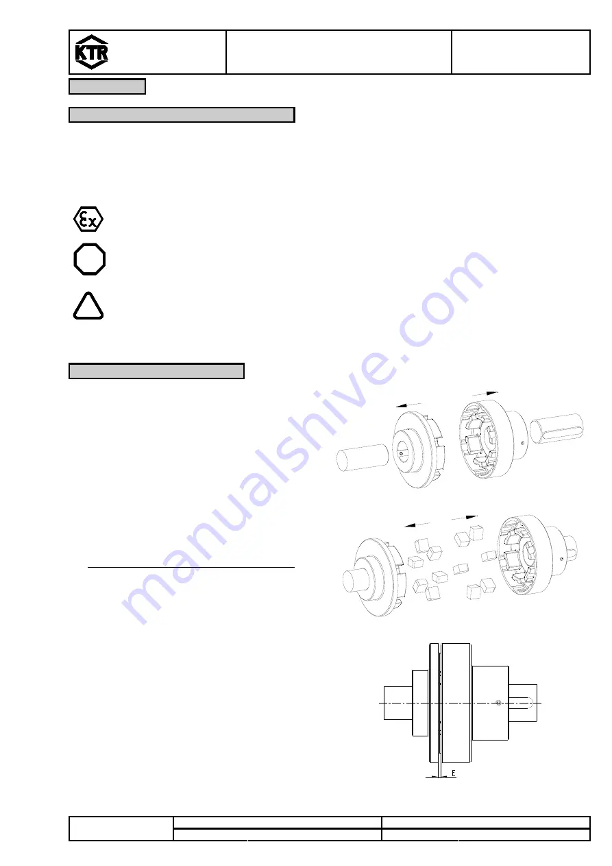
During the assembly please make sure that the E or L dimension (see table 1, 3 and 5) is
observed, so that the parts do not conact each other during the operation.
Disregarding this hint may cause damage on the coupling.
4.3 Assembly of the Type PKZ
•
Assemble the cam and the pocket section onto the
shaft of the drive and the driven side (see picture 9).
picture 9: assembly of the cam and pocket section
•
Insert the elastomer elements into the cam and the
pocket section (see picture 10).
•
Only valid for the cam section size 8 to 12!
Fasten the cam section by tightening the setscrews
DIN EN ISO 4029 with cup point (tightening torque
see table 1).
picture 10: assembly of the elastomer elements
•
Move the power packs in axial direction until the
dimension E is achieved (see picture 11).
•
If the power packs are already firmly assembled,
axial movement of the cam or the pocket section on
the shafts allows for adjusting the dimension E (see
picture 11).
•
Fasten the cam or the pocket section by tightening
the setscrews DIN EN ISO 4029 with cup point
(tightening torque see table 1).
picture 11: coupling assembly


