SKY PRO 1800 FORCED CIRCULATION MANUAL
C
C
C
22
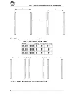
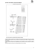
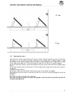
Picture 3.11-2 Fixing details scheme-a
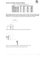
Picture 3.11-3 Fixing details scheme-b
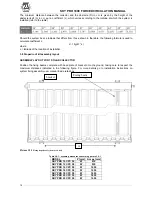
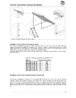
ASSEMBLY LAYOUT FOR 1 SOLAR COLLECTOR
Put the fixing beams onto the ground, taking care to respect the maximum distances indicated in the
following table 3.11-1; after that bolt the template support uprights to the fixing beams (see picture a.2) and
finally put and fix the support templates according to that indicated in the sequential figure (see picture a.1,
a.2, 3.11-4 below). P is the width of ground fixing beams. A is the distance between inside corner of the
ground fixing beams (see picture a.2). For more details go to installation instructions on its user manual.
-
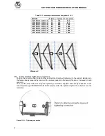
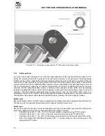
Picture a.1 Picture a.2
Table 3.11-1 : assembly measures concerning picture 3.11-3
]
m
m
[
x
a
m
A
]
m
m
[
P
L
E
D
O
M
0
0
7
0
6
8
5
C
P
C
0
1
O
R
P
Y
K
S
0
4
9
0
6
8
5
C
P
C
2
1
O
R
P
Y
K
S
0
0
1
1
0
6
8
5
C
P
C
4
1
O
R
P
Y
K
S
0
0
3
1
0
6
8
5
C
P
C
6
1
O
R
P
Y
K
S
0
0
5
1
0
6
8
5
C
P
C
8
1
O
R
P
Y
K
S
0
0
6
1
0
6
8
5
C
P
C
0
2
O
R
P
Y
K
S
0
5
6
1
0
6
8
5
C
P
C
2
2
O
R
P
Y
K
S
A
Summary of Contents for SKY PRO 10 CPC 58
Page 1: ...TECHNICAL MANUAL SOLAR COLLECTORS SKY PRO 1800 ...
Page 2: ......
Page 47: ...SKY PRO 1800 FORCED CIRCULATION MANUAL C C 47 ...
Page 49: ......

