Operation
RG268-8135-6
103
01/2019
Return change valve for direct return flow
According to the mode of operation of a given attachment, the return flow of the hydraulic oil must occur either via
the control valve (indirect return flow) or directly to the hydraulic oil tank (direct return flow). The return flow is me-
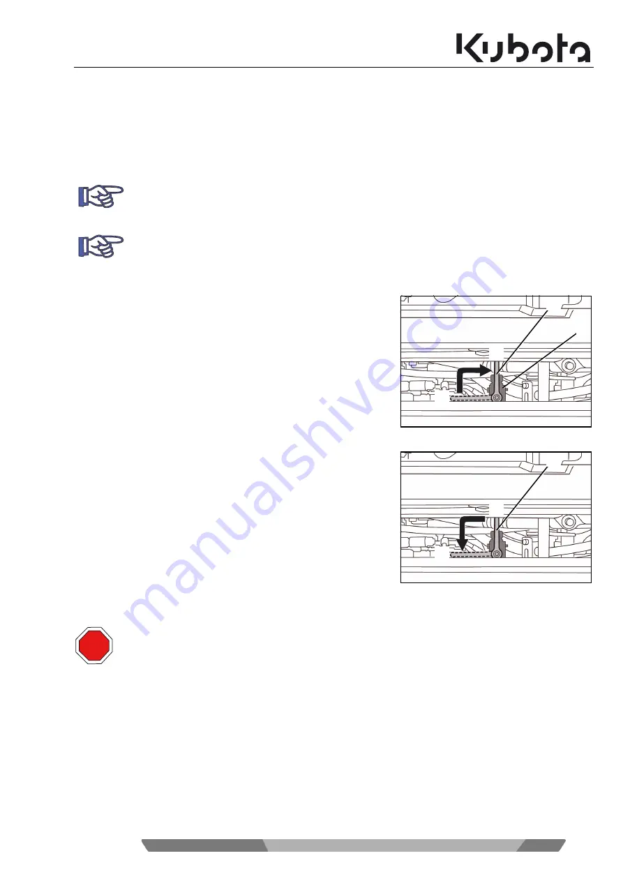
chanically switched by the change valve (see Figure 2 below).
The change valve has two settings:
When "direct return flow" is enabled, the return flow is directed from
the implement to the hydraulic oil tank via the return filter. The return
flow only occurs via the right auxiliary port 1 connector on the arm
(depending on whether the one-way hold switch was pressed).
Flip lever (1) to the vertical position (A).
The direct return flow is enabled.
When "indirect return flow" is enabled, the return flow is directed
from the implement to the return filter via the control valve and then
to the hydraulic oil tank. In this case, return flow can occur via the
left or right auxiliary port 1 connector of the arm (depending on the
position of the auxiliary port pedal and/or the rocker switch for aux-
iliary port 1).
Flip lever (1) to the horizontal position (B).
The indirect return flow is enabled.
Move the change valve to the required position depending on the
mechanism of the attachment being used (rotary or breaking).
The "direct return flow" switch position is used for hammering attachments, such as a hydraulic ham-
mer.
The "indirect return flow" switch position is used for rotating attachments, such as a rotary gripper, an
auger, etc.
If the change valve is in position "direct return flow", although an attachment with indirect return flow
has been mounted, the return flow to the hydraulic tank remains open!
This can lead to sudden movements or falling down of the attachment, even if the machine has been
switched off.
- Make sure that the change valve is switched according to the attachment.
1
A
B
2
1
A
B
STOP
Summary of Contents for 50740
Page 8: ...Tables 6 RG268 8135 6 01 2019...
Page 32: ...30 RG268 8135 6 01 2019 Safety rules...
Page 48: ...46 RG268 8135 6 01 2019 Description of the excavator...
Page 62: ...60 RG268 8135 6 01 2019 Assembly and functions...
Page 128: ...126 RG268 8135 6 01 2019 Operation...
Page 135: ...Troubleshooting RG268 8135 6 133 01 2019...
Page 136: ...134 RG268 8135 6 01 2019 Troubleshooting...
Page 139: ...Maintenance RG268 8135 6 137 01 2019...
Page 174: ...172 RG268 8135 6 01 2019 Safety inspection...
Page 193: ...Accessories RG268 8135 6 191 01 2019...
Page 194: ......


