background image

Section 2: Adjustments 

Table of Contents

4/13/21

AP-PFL5548 & AP-PFL5648 Loader Mounted Pallet Forks 319-227MK-AUS

11

Section 2: Adjustments

Fork Adjustment

Refer to Figure 2-1:

WARNING

!

To avoid serious injury or death:  

• Always adjust pallet forks an equal distance away from the 

center and as far apart as the pallet will allow. This will 

optimize load stability, protect against load shifting, and 

make handling the load safer.

• A pinching hazard exists when repositioning forks. Do not 

place hands or fingers between carrying bars and forks. 

1. Locate on a flat, level surface. Place transmission in 

park and set park brake. 

2. Rotate dump cylinders to tilt front of forks slightly 

lower at the front than at the back and lower loader 

arms until forks are slightly above ground surface.

3. Place transmission in park, set park brake, shut 

power equipment off and remove switch key.

4. Rotate locking handle (#1A) straight up.
5. Slide pallet fork (#1) to the optimized load carrying 

width by pushing or pulling on the fork near the 

carrying bars. Be sure to position locking pin (#1A) 

directly over one of the five notches in the upper 

carrying bar.

6. Lower locking handle (#1A) to seat locking pin in the 

selected notch. 

Check locking pin to be sure it has seated.

Check retaining hooks to be sure they are secured 
behind upper and lower carrying bars.

7.

Repeat steps to 6 for fork (#2). Make sure both 

forks are an equal number of notches away from the 

middle of the upper carrying bar. 

Kubota Center Logo Placement

Refer to Figure 2-2:

The Kubota logo can be lowered or removed if an 

opening is needed for accessing the skid steer or track 

loader cab or if the loader’s center hydraulic cylinder 

interferes with the Kubota logo.
1. Remove whiz nuts (#3) and bolts (#2).
2. Move Kubota Logo (#1) down to the four lower 

mounting holes and reattach with existing 

3/8"-16 x 1" GR5 hex flange bolts (#2) and whiz 

nuts (#3). Tighten nuts to the correct torque. Remove 

logo and store for safe keeping if lower location also 

interferes.

NOTE:  

Forks will adjust easier if glide surfaces are 

kept lubricated. See 

“Pallet Fork Contact Points” 

on page 17 for lubricating instructions.

Fork Adjustment

Figure 2-1

Kubota Logo Placement

Figure 2-2

1A

2A

1

2

Upper Carrying Bar

Lower Carrying Bar

All PFL Series have 5 notches on each side 

for positioning the pallet forks.

Retaining 

Hooks

74596

Lower Mounting 

Location

74601

Summary of Contents for AP-PFL5548

Page 1: ...rench Language please see your Kubota dealer Read the Operator s Manual entirely When you see this symbol the subsequent instructions and warnings are serious follow without exception Your life and the lives of others depend on it 74906 Loader Mounted Pallet Forks AP PFL5548 AP PFL5648 319 227MK AUS Operator s Manual Printed 4 13 21 ...

Page 2: ...rdered the weights and measurements are no longer accurate for your machine Update the record by adding the machine weight and measurements provided in the Specifications Capacities Section of this manual with the Option s weight and measurements Dealer Contact Information Model Number Serial Number Manufactured Year Machine Height Machine Length Machine Width Machine Weight Delivery Date First Op...

Page 3: ...et Forks 319 227MK AUS Table of Contents Important Safety Information 1 Safety at All Times 1 Look for the Safety Alert Symbol 1 Safety Labels 6 Introduction 8 Application 8 Using This Manual 8 Terminology 8 Definitions 8 Owner Assistance 8 Serial Number Manufactured Year 8 Section 1 Assembly Set Up 9 Fork Installation 9 Step Relocation 9 Hook Up Pallet Fork 10 Section 2 Adjustments 11 Fork Adjust...

Page 4: ...your smart phone open the App point your phone on the QR code and take a picture Dealer QR Locator The QR code on the left will link you to available dealers for Kubota products Refer to Parts Manual QR Locator on this page for detailed instructions Table of Contents 4 13 21 AP PFL5548 AP PFL5648 Loader Mounted Pallet Forks 319 227MK AUS See previous page for Table of contents ...

Page 5: ...hem Keep children out of the work area and under the watchful eye of a responsible adult Be alert and shut the attachment and skid steer track loader down if children enter the work area Never carry children on the power machine or attachment There is not a safe place for them to ride They may fall off and be run over or interfere with the control of the power machine Never allow children to opera...

Page 6: ... s Manual for additional information Work on a level surface in a clean dry area that is well lit Lower attachment to the ground and follow all shutdown procedures before leaving the operator s seat to perform maintenance Do not work under any hydraulically supported equipment It can settle suddenly leak down or be lowered accidentally If it is necessary to work under the equipment securely suppor...

Page 7: ...machine should be upset If ROPS is in the locked up position fasten seat belt snugly and securely to help protect against serious injury or death from falling and machine overturn Avoid High Pressure Fluids Escaping fluid under pressure will penetrate the skin or eyes causing serious injury Relieve all residual pressure before disconnecting hydraulic lines or performing work on the hydraulic syste...

Page 8: ...rators are required wear a respirator approved for protection against crystalline silica containing dust Do not alter respirator in any way Workers who use tight fitting respirators can not have beards mustaches which interfere with the respirator seal to the face If possible change into disposable or washable work clothes at the work site shower and change into clean clothing before leaving the w...

Page 9: ...Important Safety Information 4 13 21 5 This page left blank intentionally ...

Page 10: ...find your nearest dealer visit our dealer locator at www landpride com 3 Some new equipment installed during repair requires safety labels to be affixed to the replaced component as specified by Kubota When ordering new components make sure the correct safety labels are included in the request 4 Refer to this section for proper label placement To install new labels a Clean surface area where label...

Page 11: ...nformation Table of Contents 4 13 21 AP PFL5548 AP PFL5648 Loader Mounted Pallet Forks 319 227MK AUS 7 74596 74597 74597 838 293C Warning Read Operator s Manual 858 971C Warning Misuse Hazard 818 798C Pinch Point Hazard ...

Page 12: ...ota welcomes you to the growing family of new product owners This pallet fork has been designed with care and built by skilled workers using quality materials Proper assembly maintenance and safe operating practices will help you get years of satisfactory use from this attachment Application The Kubota PFL5548 and PFL5648 pallet forks have uses and applications in farming ranching construction sit...

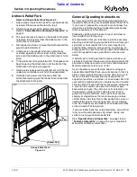
Page 13: ...ing on the fork near carrying bars 3 4 until locking pin 1 is positioned over one of the pin notches 4 Lower locking pin handle 1 to seat pin in the selected notch Make sure locking pin is seated and retaining hooks A B are secured behind the carrying bars 5 Repeat steps 1 4 for the second fork but slide the second fork to the left Step Relocation Refer to Figure 1 1 The pallet fork is shipped fro...

Page 14: ...h fit up frequently An improper fit up can cause the attachment to come loose from the loader hitch plate and fall Always shut power machine down following the Shutdown Procedure provided in this manual before leaving the operator s station Refer to Power Machine Shutdown Procedure on page 14 1 If needed pull locking handles up on loader hitch until locking pins are fully raised 2 Carefully drive ...

Page 15: ... of the five notches in the upper carrying bar 6 Lower locking handle 1A to seat locking pin in the selected notch Check locking pin to be sure it has seated Check retaining hooks to be sure they are secured behind upper and lower carrying bars 7 Repeat steps 1 to 6 for fork 2 Make sure both forks are an equal number of notches away from the middle of the upper carrying bar Kubota Center Logo Plac...

Page 16: ...r gangrene may result DO NOT DELAY Check pallet fork frequently to make sure it is properly attached to the loader hitch forks are secured to the upper and lower carrying bars and fork locking pins are seated in their notches Consult your power machine Operator s Manual for operating capacity lifting capacity and operating specifications Exceeding rated capacities and specifications can result in ...

Page 17: ...ting from the skid steer or track loader Follow manufacturer s recommendations when dismounting and parking the machine Always store attachment in a secure position so that it will not fall over Always stack pallets in such a manner that they will not tip or fall Transport Safety DANGER To avoid serious injury or death Keep attachment loader arms and or load away from overhead electrical power lin...

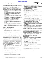
Page 18: ...e Power Unit IMPORTANT On heavy loads the center of gravity should not be positioned farther than 24 61 cm away from the vertical face of the forks Picking up heavy loads positioned farther away can damage the unit and void its warranty 9 Position load at a safe traveling height before moving Two to four inches 5 cm to 10 cm above the floor is recommended traveling height Traveling With a Load 1 P...

Page 19: ...eer or track loader and starting it up We recommend that you take time to practice securely attaching and detaching your pallet fork to and from your skid steer or track loader hitch It is also important to practice lifting lowering maneuvering and placing an empty pallet on a level site until you gain the confidence and skill needed to have a good feel in what you are doing If attachment is to be...

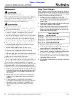
Page 20: ...life of any implement With careful inspection and routine maintenance you can avoid costly downtime and repair 1 After using your pallet fork for a few lifts check forks to make sure they are still secured and check pallet fork to make sure it is still properly attached to the loader hitch 2 Check forks to make sure they are not damaged broken or worn excessively Repair or replace as needed 3 Alwa...

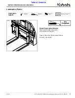
Page 21: ...llet Fork Contact Points Top face of upper carrying bar Face of lower carrying bar Type of Lubrication Multi purpose Grease Quantity As needed Lubrication Points 74596 As Required 50 Hrs Multi purpose spray lube Multi purpose grease lube Multi purpose oil lube Intervals in hours at which lubrication is required Lubrication Legend ...

Page 22: ... kg 5500 2500 in cm Lift capacity is based on load being 24 61 from face of frame Cross bar Load must be palletized and supported by two forks Class ll Frame Width in cm 46 117 Frame Height in cm 40 102 Tine Thickness in cm 1 3 4 4 4 Tine Width in cm 4 10 2 Tine Length in m 48 1 22 Fork Positioning Lock Spring Loaded Toggle PFL5548 PFL5648 Models 40 102 cm 46 117 cm 50 127 cm 24 61 cm PFL5548 57 1...

Page 23: ... your skid steer or track loader Rear spill guard Keep loads from slipping backwards Easy adjustable forks Forks slide easily on carrying bars from one position to another Simply rotate locking handles up and slide forks to their new positions Rotate locking handles down to secure forks in their new position Capacity 5 500 lbs 2495 kg Fork length 48 1 22m Meets most needs for material handling on ...

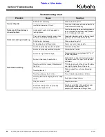
Page 24: ... out of the ground Never use forks to pry objects Pallet load is shifting Load is not properly secured on pallet Secure load to pallet Load is not properly centered on pallet Center load on pallet Load is being carried too high Recommended carrying height is 2 to 4 above the ground Forks are too close to each other Adjust forks an equal distance away from the center and as far apart as the pallets...

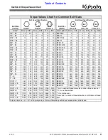
Page 25: ...235 170 M16 X 2 145 105 225 165 315 230 5 8 11 130 97 205 150 285 210 M16 X 1 5 155 115 240 180 335 245 5 8 18 150 110 230 170 325 240 M18 X 2 5 195 145 310 230 405 300 3 4 10 235 170 360 265 510 375 M18 X 1 5 220 165 350 260 485 355 3 4 16 260 190 405 295 570 420 M20 X 2 5 280 205 440 325 610 450 7 8 9 225 165 585 430 820 605 M20 X 1 5 310 230 650 480 900 665 7 8 14 250 185 640 475 905 670 M24 X ...

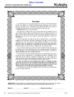
Page 26: ...amaged by accident or lack of normal maintenance or care or which has been repaired or altered in a way which adversely affects its performance or reliability or which has been used for a purpose for which the product is not designed Misuse also specifically includes failure to properly maintain oil levels grease points and driveline shafts Claims under this Warranty should be made to the dealer w...

Page 27: ...ms all representations and warranties whether express or implied including but not limited to warranties of merchantability and fitness for a particular purpose and Kubota shall not be liable for any damages whether compensatory direct indirect incidental special or consequential arising out of or in connection with the use of this publication or in the information therein The Product s described ...

Page 28: ...CA 95240 209 334 9910 Midwest Division Telephone 31700 W 207th ST Edgerton KS 66021 913 215 5915 Central Division Telephone 14855 FAA Blvd Fort Worth TX 76155 817 571 0900 Northern Division Telephone 6300 at One Kubota Way Groveport OH 43125 614 835 1100 Southeast Division Telephone 1025 Northbrook Parkway Suwanee GA 30024 770 995 8855 ...

Reviews: