background image

14

OPERATING THE ENGINE

B

Regeneration Operating Procedure

Operating Procedure for Auto Regeneration Mode

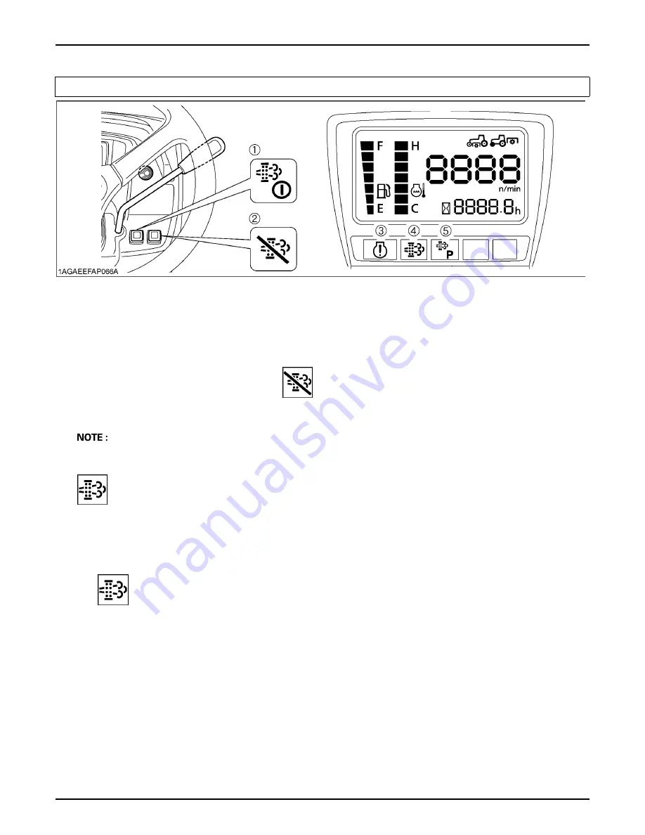
(1) Parked regeneration switch
(2) DPF INHIBIT switch

(3) Engine warning indicator
(4) Regeneration indicator

(5) Parked regeneration indicator

1.

Start the engine.
(Make sure that the DPF INHIBIT switch lamp 

  is "OFF".)

 
Switch lamp OFF: Auto Regeneration Mode activated.
Switch lamp ON: Regeneration Inhibit Mode activated.

A

When the engine is started, the "Auto Regeneration" mode is automatically activated.

A

"Regeneration Inhibit" mode is activated, when the DPF INHIBIT switch is pushed after the engine is started.

2.

When a specific amount of PM has built up in the DPF, the regeneration indicator turns "ON".
Continue to operate the tractor, and the regeneration process will begin automatically, make sure you are
working in a safe area as DPF and exhaust temperature will rise.
When the regeneration cycle has completed, the regeneration indicator turns "OFF".

IMPORTANT:

A

When ambient temperature is so low or when working with such extraordinary use of electricity that the
regeneration conditions are not satisfied, the regeneration indicator starts flashing.

If the regeneration indicator turns "ON" for a while and then starts flashing, keep on working and rev 
up the engine to the maximum rpm so that the regeneration indicator stops flashing and remains "ON".

Summary of Contents for B2650

Page 1: ...1AGAEEFAP0010 1AGAEEFAP0010 B2650 B3350 B3350SU MODELS OPERATOR S MANUAL B 2 6 5 0 B 3 3 5 0 B 3 3 5 0 S U READ AND SAVE THIS MANUAL...

Page 2: ......

Page 3: ...y them however are unified by one central commitment KUBOTA makes products which taken on a national scale are basic necessities Products which are indispensable products intended to help individuals...

Page 4: ...API ASABE ASTM DIN DT fpm Hi Lo HST m s PTO RH LH ROPS rpm r s SAE SMV The above IMPORTANT text for the spark arrester is applicable to Model B2650 alone California Proposition 65 WARNING Engine exhau...

Page 5: ...ontrol Off Position Disengaged Power Take Off Control On Position Engaged Differential Lock Position Control Raised Position Position Control Lowered Position Engine Warning 3 Point Lowering Speed Con...

Page 6: ...em It will give you long satisfactory service To obtain the best use of your tractor please read this manual carefully It will help you become familiar with the operation of the tractor and contains m...

Page 7: ...s 18 Tips on DPF Regeneration 21 STARTING THE ENGINE 21 Block Heater Option 24 STOPPING THE ENGINE 25 WARMING UP 25 Warm up Transmission Oil at Low Ambient Temperatures 25 JUMP STARTING 26 OPERATING T...

Page 8: ...e of Power Steering 40 Electrical Outlet 41 PTO 42 PTO OPERATION 42 PTO Select Lever 42 PTO Clutch Lever 43 PTO Clutch Lever 43 LCD Monitor Message 44 Stationary PTO 44 3 POINT HITCH DRAWBAR 45 3 POIN...

Page 9: ...on Fluid Level 65 Checking Coolant Level 66 Cleaning Evacuator Valve 66 Cleaning Grill and Radiator Screen 67 Checking DPF Muffler 67 Checking Brake Pedal 67 Checking Gauges Meter and Easy Checker TM...

Page 10: ...ing Injection Pump 80 Checking Turbocharger 80 EVERY 1 YEAR 81 Replacing Air Cleaner Primary Element and Secondary Element 81 Checking Exhaust manifold 81 EVERY 2 YEARS 81 Flushing Cooling System and...

Page 11: ...ear of the tractor to reduce the risk of upsets When using the front loader put an implement or ballast on the 3 point hitch to improve stability Follow the safe operating procedures specified in the...

Page 12: ...use that operator presence controls are functioning correctly Test safety systems See Checking Engine Start System in EVERY 50 HOURS in PERIODIC SERVICE section Do not operate unless they are function...

Page 13: ...of the steering wheel 4 Avoid disengaging the clutch or changing gears speed when climbing or going down a slope If on a slope disengaging the clutch or changing gears to neutral could cause loss of c...

Page 14: ...ning may allow the tractor to move and could cause injury or death 1 Wait until all moving components have completely stopped before getting off the tractor connecting disconnecting adjusting cleaning...

Page 15: ...d fire extinguisher handy at all times 7 Disconnect the battery s ground cable before working on or near electric components 8 To avoid the possibility of battery explosion do not use or charge the re...

Page 16: ...not disconnect nor attempt to repair fuel lines sensors or any other components between the high pressure fuel pump and injectors on engines with high pressure common rail fuel system 18 To avoid haz...

Page 17: ...7 SAFE OPERATION 7 DANGER WARNING AND CAUTION LABELS...

Page 18: ...SAFE OPERATION 8...

Page 19: ...9 SAFE OPERATION...

Page 20: ...r warning and caution labels with new labels from your local KUBOTA Dealer 4 If a component with danger warning and caution label s affixed is replaced with new part make sure new label s is are attac...

Page 21: ...ial numbers now and record them in the space provided C Warranty This tractor is warranted under the KUBOTA Limited Express Warranty a copy of which may be obtained from your selling dealer No warrant...

Page 22: ...SERVICING OF TRACTOR 2 1 ROPS identification ROPS Serial No 1 Diesel Particulate Filter DPF serial number...

Page 23: ...RC 80min CCD 430A Capacities Fuel tank L U S gals 27 7 1 Engine crankcase with filter L U S qts 4 0 4 2 4 8 5 1 Engine coolant L U S qts 4 3 4 5 Transmission case L U S gals 15 4 0 Dimensions Overall...

Page 24: ...arter inching valve Pump capacity L min gals min 33 1 8 7 3 point hitch SAE Category 1 Max lift force At lift points kg lbs 970 2139 24 in behind lift point kg lbs 760 1676 PTO Rear PTO SAE 1 3 8 6 sp...

Page 25: ...ar 12 4 16 Farm 13 6 16 Turf Range gear shift lever km h mph km h mph Forward Low 0 to 5 7 0 to 3 6 0 to 6 0 0 to 3 7 Middle 0 to 9 3 0 to 5 8 0 to 9 8 0 to 6 1 High 0 to 21 9 0 to 13 6 0 to 23 0 0 to...

Page 26: ...g trees primarily in case a rear mounted tree grab crane is mounted at the rear of the tractor b penetrating objects in the operator s enclosure primarily in case a winch is mounted at the rear of the...

Page 27: ...ary Bottom plow Max size mm in 305 12 x 2 Disc plow Max size mm in 559 22 x 2 Cultivator Max size mm in 1524 60 1 Row Disc harrow Max harrowing width Max weight mm in kg lbs 1676 66 250 550 Sprayer Ma...

Page 28: ...trols ILLUSTRATED CONTENTS 1 Hazard light switch 31 2 Turn signal light switch 31 3 Head light switch 31 4 Parking brake lever 34 5 Speed set lever B2650 B3350 only 35 6 Hand throttle lever 34 7 Parke...

Page 29: ...indicator B3350 B3350SU only 21 4 Master system warning indicator 36 5 Engine warning indicator B3350 B3350SU only 36 6 Regeneration indicator B3350 B3350SU only 12 7 Parked regeneration indicator B3...

Page 30: ...h lowering speed knob 51 12 Speed control pedal 35 4 Differential lock pedal 39 13 Loader control lever 52 5 Range gear shift lever L M H 33 14 Loader lock lever 53 6 PTO clutch lever 43 15 Front whee...

Page 31: ...d to the ground Check item Walk around inspection Check engine oil level Check transmission oil level Check coolant level Clean grill and radiator screen Check DPF muffler B3350 B3350SU only Check air...

Page 32: ...filter components reach temperatures hot enough to burn people or ignite or melt common materials A Keep tractor away from people animals or structures which may be susceptible to harm or damage from...

Page 33: ...ring the warning signs may cause DPF and engine damage BDPF Regeneration Process DPF regeneration process can be performed by choosing from Auto Regeneration or Regeneration inhibit mode according to...

Page 34: ...ed after the engine is started 2 When a specific amount of PM has built up in the DPF the regeneration indicator turns ON Continue to operate the tractor and the regeneration process will begin automa...

Page 35: ...icator starts flashing Start the regeneration referring to PM warning level 1 above Now the parked regeneration indicator starts flashing and the parked regeneration can also be started If the regener...

Page 36: ...akes shorter than 4 hours or so for the regeneration indicator to go out and light up again 2 Parked regeneration indicator starts flashing D Buzzer Sounding every 5 seconds 3 Immediately discontinue...

Page 37: ...ndicator 1 Start the engine 2 Press the DPF INHIBIT switch and the switch lamp illuminates Switch lamp ON Regeneration Inhibit Mode selected Switch lamp OFF Auto Regeneration Mode selected 3 When the...

Page 38: ...follow the Operating Procedure for Parked Regeneration Buzzer Sounding every 5 seconds PM warning level 2 2 The Parked regeneration indicator starts flashing Buzzer Sounding every 3 seconds PM warning...

Page 39: ...akes shorter than 4 hours or so for the regeneration indicator to go out and light up again 2 Parked regeneration indicator starts flashing D Buzzer Sounding every 5 seconds 3 Immediately discontinue...

Page 40: ...t the parking brake 3 Set the speed control pedal to NEUTRAL position 4 Set the speed set lever to OFF position 5 Set the PTO clutch lever to OFF position 6 Lower the implement to the ground 7 Turn st...

Page 41: ...xhaust temperature and engine speed A It is recommended to do the regenerating while the engine is warm and at high revolution A Do not unnecessarily start and interrupt the regeneration process Other...

Page 42: ...OFF DISENGAGE 3 Place the speed set lever in OFF position except B3350SU Place the speed control pedal in the NEUTRAL position Place the range gear shift lever L M H in the NEUTRAL position 1 Range ge...

Page 43: ...in NEUTRAL position B3350SU only 1 Hydraulic control lever A DOWN B SLOW DOWN N NEUTRAL C SLOW UP D UP 6 Set the throttle lever to about 1 2 way 1 Hand throttle lever INCREASE DECREASE 7 Insert the k...

Page 44: ...e engine fails to start turn off the key for 30 seconds Then repeat steps 8 and 9 To protect the battery and the starter make sure that the starter is not continuously turned for more than 30 seconds...

Page 45: ...aulic oil serves as transmission fluid In cold weather the oil will be cold which will increase oil viscosity This can cause delayed oil circulation or abnormally low hydraulic pressure for some time...

Page 46: ...mp to the positive red or pos terminal of the dead battery and clamp the other end of the same cable to the positive red or pos terminal of the helper battery 5 Clamp the other cable to the negative b...

Page 47: ...ly observed in the case of new tractors BChanging Lubricating Oil for New Tractors The lubricating oil is especially important in the case of a new tractor The various parts are not broken in and are...

Page 48: ...hair pins BTo Raise the ROPS to Upright Position 1 Remove both hair pins and set bolts 2 Raise ROPS to the upright position maintain a hold on the ROPS To avoid personal injury A Raise the ROPS slowly...

Page 49: ...od posture and minimizes risks from whole body vibration BOperator s Seat To avoid personal injury A Make sure that the seat is completely secured after each adjustment A Do not allow any person other...

Page 50: ...ury A Always use the seat belt when the ROPS is installed A Do not use the seat belt if a foldable ROPS is down or there is no ROPS Adjust the seat belt for proper fit and connect to the buckle The se...

Page 51: ...l stay on C Turn Signal with Hazard Light Switch Off 1 To indicate a right turn without hazard lights hazard switch off turn the turn signal switch clockwise 2 To indicate a left turn without hazard l...

Page 52: ...2 and 4 wheel drive Be aware of the difference and use carefully A When driving on icy wet or loose surfaces make sure the tractor is correctly ballasted to avoid skidding and loss of steering control...

Page 53: ...the range gear shift lever A If it is difficult to shift the range gear shift lever into L M or H from neutral position 1 Slightly depress the speed control pedal to rotate the gears inside of transmi...

Page 54: ...avoid damage of transmission when front wheel drive lever is not smoothly shifted slightly step forward or rearward on speed control pedal A Tires will wear quickly if front wheel drive is engaged on...

Page 55: ...personal injury A Pull the speed set lever completely to the up position before starting the engine A Do not use the speed set device when driving on the road A Be sure to connect both the left and t...

Page 56: ...tely stop the engine and find the cause as shown below Never operate the tractor while Easy Checker TM lamp is on A For checking and servicing of your tractor consult your local KUBOTA Dealer for inst...

Page 57: ...Temperature Gauge To avoid personal injury or death A Do not remove radiator cap until coolant temperature is well below its boiling point Then loosen the cap slightly to relieve any pressure before r...

Page 58: ...ion on the dial 2 The hourmeter indicates in 5 digits the hours the tractor has been used the last digit indicates 1 10 of an hour BChanging Display Mode 1 The LCD monitor give several different displ...

Page 59: ...ersonal injury or death due to loss of steering control A Do not operate the tractor at high speed with differential lock engaged A Do not attempt to turn with the differential lock engaged A Be sure...

Page 60: ...f ditches or banks which may collapse under the weight of the tractor Especially when the ground is loose or wet 1 Slow down for slopes rough ground and sharp turns especially when transporting heavy...

Page 61: ...41 OPERATING THE TRACTOR BElectrical Outlet An electrical outlet is supplied for use with implement and electrical equipment 1 Accessory electrical outlet 10A...

Page 62: ...select lever to Mid PTO position and the PTO clutch lever to the ON position C Mid Rear PTO To use mid and rear PTO at the same time shift the PTO select lever to mid rear PTO position and the PTO cl...

Page 63: ...position the engine will stop regardless of the position of the PTO select lever This is because the tractor is equipped with Operator Presence Control OPC system BPTO Clutch Lever 1 The tractor has...

Page 64: ...locks at the tires 2 Make sure the shift levers are at NEUTRAL and start the engine 3 Set the PTO select lever to rear only position B2650 B3350 only 4 Set the PTO clutch lever to engage ON 5 Set the...

Page 65: ...45 3 POINT HITCH DRAWBAR 3 POINT HITCH DRAWBAR 1 Top link 2 Top link holder 3 Lifting rod Left 4 Telescopic stabilizers 5 Lower link 6 Lifting rod Right 7 Drawbar...

Page 66: ...46 3 POINT HITCH DRAWBAR 1 Top link 2 Lifting rod Left 3 Check chains 4 Turnbuckle 5 Lower link 6 Drawbar 7 Lifting rod Right 8 Top link holder...

Page 67: ...efore attaching or detaching implement locate the tractor and implement on a firm flat and level surface A Whenever an implement or other attachment is connected to the tractor 3 point hitch check ful...

Page 68: ...rily insert the set pin through any one of the 8 holes on the outer tube that align with one of the holes on the inner bar both stabilizers will be locked If the set pin is inserted through the slot t...

Page 69: ...t above the drawbar Doing so could cause the tractor to tip over rearward causing personal injury or death BAdjusting Drawbar Length When towing an implement use of B hole in drawbar is recommended Th...

Page 70: ...implement to the desired height move the lever back to NEUTRAL position The lever position B or C enables you to control the valve with ease in increments of approximately 1 4 inches at the lower link...

Page 71: ...Type Outlet Hydraulic block type outlet is useful when adding hydraulically operated equipment such as front end loader front blade etc When an implement is attached 1 Remove the block cover 2 Attach...

Page 72: ...port to the Head End side port of the hydraulic cylinder A Make the following connections when using this valve to take off hydraulic power for the hydraulic cylinder BLoader Remote Control Valve Lev...

Page 73: ...The valve lock is to prevent accidental actuation when implement is not in use or during transport The control valve is equipped with a valve lock feature The control valve is locked in the LOCK posit...

Page 74: ...B2650 B3350 Position control B3350SU Hydraulic control YES NO Loose B2650 B3350 Insert the set pin through the slot on the outer tube that align with one of the holes on the inner bar B3350SU Adjust...

Page 75: ...any machine elements for servicing or adjustment securely support them with stands or suitable blocking beforehand A Never operate tractor with a loose rim wheel or axle BFront Wheels Front tread widt...

Page 76: ...200 m 200 yards and 10 times of shuttle movement by 5 m 5 yards and thereafter according to service interval See MAINTENANCE section To avoid personal injury or death A Before jacking up the tractor p...

Page 77: ...7 TIRES WHEELS AND BALLAST BTreads B2650 B3350 B3350SU B3350 B3350SU only Front 7 12 Farm 24x8 50 14 Turf 23x8 50 14 Ind Rear 12 4 16 Farm 13 6 16 Turf 12 4 16 Ind Front 25x8 50 14 Ind Rear 15 19 5 In...

Page 78: ...rear wheels if needed to improve traction or for stability The amount of rear ballast should be matched to job and the ballast should be removed when it is not needed The weight should be added to th...

Page 79: ...Hr 78 6 Front axle case oil Change every 400 Hr 80 7 Front axle pivot Adjust every 400 Hr 80 8 Engine start system Check every 50 Hr 69 9 Greasing every 50 Hr 68 10 Wheel bolt torque Check every 50 Hr...

Page 80: ...Warranty Statement in detail 16 Radiator hose and clamp Check every 200 Hr 77 Replace every 2 year 82 17 Fuel line Check every 100 Hr 74 Replace every 2 year 82 3 18 Intake air line Check every 200 Hr...

Page 81: ...4 3 L 4 5 U S qts Fresh clean soft water with anti freeze 3 Engine crankcase with filter 4 0 L 4 2 U S qts 4 8 L 5 1 U S qts Engine oil Refer to next page Above 25 77 SAE30 SAE10W 30 or 15W 40 10 to...

Page 82: ...er UDT 2 For an enhanced ownership experience we highly recommend Super UDT 2 to be used instead of standard hydraulic transmission fluid Super UDT 2 is a proprietary KUBOTA formulation that deliverie...

Page 83: ...could result A Support hood with other hand while unlocking support link BHood C Open the hood 1 To open the hood twist the mascot 2 Open the hood by holding its bottom with both hands 3 Hold the hoo...

Page 84: ...and Refueling To avoid personal injury or death A Do not smoke while refueling A Be sure to stop the engine before refueling 1 Turn the key switch to ON check the amount of fuel by fuel gauge 2 Fill f...

Page 85: ...tion A When using an oil of different maker or viscosity from the previous one remove all of the old oil Never mix two different types of oil A If oil level is low do not run engine BChecking Transmis...

Page 86: ...add soft water only up to the full level In case of leakage add anti freeze and soft water in the specified mixing ratio up to the full level See Flushing Cooling System and Changing Coolant in EVERY...

Page 87: ...nd wait long enough until it is cooled down Check the DPF muffler and its surroundings for build up of anything flammable Otherwise a fire may result BChecking Brake Pedal 1 Inspect the brake pedals f...

Page 88: ...rectly to battery wiring connectors electrical components or instrument panel Inspect the following Regularly 1 Check wiring for chafed or cracked insulation 2 Check wiring harness clamps Replace if n...

Page 89: ...3 Turn the key to START position 4 The engine must not crank 5 If it cranks consult your local KUBOTA Dealer for this service C Test Switches for the operator s seat and the PTO clutch lever 1 Sit on...

Page 90: ...ds some servicing If the battery is weak the engine will be difficult to start and the lights will be dim It is important to check the battery periodically C How to read the indicator Check the batter...

Page 91: ...every 3 months in hot seasons and once every 6 months in cold seasons BCleaning Air Cleaner Primary Element To avoid personal injury A Be sure to stop the engine and remove the key before cleaning air...

Page 92: ...hecking fuel lines and fuel filter A Check the fuel lines periodically The fuel lines are subject to wear and aging Fuel may leak out onto the running engine causing a fire A Protect your hands when u...

Page 93: ...gine and remove the key 2 Apply moderate thumb pressure to belt between pulleys 3 If tension is incorrect loosen the alternator mounting bolts and using a lever placed between the alternator and the e...

Page 94: ...hin acceptable limits 4 Retighten the lock nut BChecking Fuel Line 1 Check to see that all lines and hose clamps are tight and not damaged 2 If hoses and clamps are found worn or damaged replace or re...

Page 95: ...the engine oil up to the prescribed level A To prevent serious damage to the engine use only a KUBOTA genuine filter BChanging Engine oil To avoid personal injury or death A Be sure to stop the engine...

Page 96: ...a filter wrench tighten it an additional 1 turn only 4 After the new filter has been replaced fill the transmission oil up to the upper limit on the dipstick 5 After running the engine for a few minut...

Page 97: ...cked C Precaution at Overheating Take the following actions in the event the coolant temperature is nearly or more than the boiling point what is called Overheating 1 Park the tractor in a safe place...

Page 98: ...ion Fluid To avoid personal injury or death A Allow engine to cool down sufficiently oil can be hot and can burn 1 To drain the used oil remove the drain plug at the bottom of the transmission case an...

Page 99: ...completely into the oil pan 2 After draining reinstall the drain plugs 3 Remove the oil filter 4 Put a film of clean transmission oil on the rubber seal of the new filter 5 Quickly tighten the filter...

Page 100: ...vel surface 2 To drain the used oil remove the right and left drain plugs and filling plug at the front axle case and drain the oil completely into the oil pan 3 After draining reinstall the drain plu...

Page 101: ...t 3 After all coolant is drained close the drain cock and reinstall the drain plug 4 Fill with clean soft water and cooling system cleaner 5 Follow directions of the cleaner instruction 6 After flushi...

Page 102: ...e inside 3 Mixing the LLC Premix 50 LLC with 50 clean soft water When mixing stir it up well and then fill into the radiator 4 The procedure for the mixing of water and antifreeze differs according to...

Page 103: ...been used for a long period of time C Bleeding procedure is as follows 1 Fill the fuel tank with fuel 2 Start the engine and run for about 30 seconds and then stop the engine BDraining Clutch Housing...

Page 104: ...m If any of the fuses should blow replace with a new one of the same capacity A Before replacing a blown fuse determine why the fuse blew and make any necessary repairs Failure to follow this procedur...

Page 105: ...15 Flasher Hazard 11 5 Spare Fuse 12 10 Spare Fuse 13 15 Spare Fuse 14 30 Spare Fuse 15 30 Starter Relay 16 15 Reforming Glow 17 Slow blow fuse Check circuit against wrong battery connection B2650 FU...

Page 106: ...a dry place where the tractor is sheltered from the elements Cover the tractor 9 Store the tractor indoors in a dry area that is protected from sunlight and excessive heat If the tractor must be store...

Page 107: ...ractor is going to be used Insufficient engine power A Insufficient or dirty fuel A The air cleaner is clogged A Check the fuel system A Clean or replace the element Engine stops suddenly A Insufficie...

Page 108: ...diately contact your local KUBOTA Dealer for repairs 1 Master system warning indicator 2 Error code B3350 B3350SU Displayed error code Trouble Operator s action Err 2 Fuel sensor trouble Contact your...

Page 109: ...urther detail A Rear Work Light High visibility for night work A Front end weights For front ballast A Mounting Kit Front end weights To mount Front end weights A Engine Block Heater For extremely col...

Page 110: ...oling System and Coolant 81 Front Axle Case Oil 80 Front Axle Pivot 4WD 80 Front Ballast 58 Front Wheel Drive Lever 34 Front Wheels 55 Fuel Filter 72 Fuel Filter Element 80 Fuel Gauge 37 Fuel Hose 82...

Page 111: ...Stationary PTO 44 Stopping 36 Telescopic Stabilizers 48 Tilt Steering Adjustment 30 Tips on DPF Regeneration 21 To Fold the ROPS 27 To Raise the ROPS to Upright Position 28 Toe in 78 Top Link 47 Top L...

Page 112: ...English U S A Code No 6C410 6311 1 B 2 6 5 0 B 3 3 5 0 B 3 3 5 0 S U KUBOTA Corporation 2013 PRINTED IN JAPAN...

Reviews: