background image

PERIODIC SERVICE

46

ENGLISH

3. Turn the key to the "START" position.
4. The engine should not crank.

Test 3

 (Engine Safety Control)

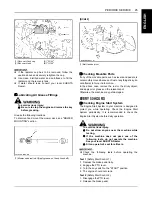
1. Open the hood.
2. Sit on the operator's seat.
3. Depress the brake pedal fully.
4. Turn the key to the "START" position.
5. The engine should not crank.

B

Checking OPC System

The OPC (Operator Presence Control) system in your
machine is designed to protect you while operating.
Check the OPC system periodically. It is recommended to
check the OPC system before daily operation.

To avoid serious injury:

A

Do not allow anyone near the machine while
testing.

A

If the machine does not pass one of the
following tests, do not operate the machine.
See your local KUBOTA Dealer.

A

Check the following tests before operating the
machine.

Test 1

 (Seat Safety Control 1)

1. Run the engine at half throttle.
2. Engage the PTO lever.
3. Stand up. (DO NOT GET OFF THE MACHINE.)
4. Engine should shut off.

Test 2

 (Seat Safety Control 2)

1. Run the engine at half throttle.
2. Disengage the PTO lever.
3. Release the brake pedal.

4. Stand up. (DO NOT GET OFF THE MACHINE.)
5. Engine should shut off.

B

Checking PTO Control System

The PTO control system in your machine is designed to
protect you while operating. Check the PTO control
system periodically. It is recommended to check the PTO
control system before daily operation.

To avoid serious injury:

A

Do not allow anyone near the machine while
testing.

A

If the machine does not pass one of the
following tests, do not operate the machine.
See your local KUBOTA Dealer.

A

Sit on operator's seat for all tests.

A

Check the following tests before operating the
machine.

Test 1

 (KUBOTA Reverse Awareness system

(KRA system) 1)
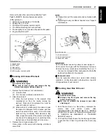
1. Start and run the engine at half throttle.
2. Engage the PTO lever.
3. Press slightly on reverse side of speed control pedal.
4. Engine should shut off.

Test 2

 (KUBOTA Reverse Awareness system

(KRA system) 2)
1. Start and run the engine at 1/4 throttle.
2. Engage the PTO lever.
3. Press the KRA system override switch.
4. The KRA indicator light should flash.
5. Press slightly on the reverse side of speed control

pedal.

6. Engine should not shut off.

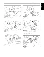
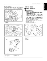
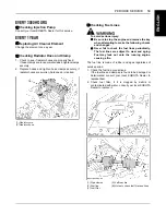
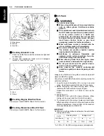
(1) Brake pedal
(2) PTO lever
(3) Key switch
(4) Throttle lever

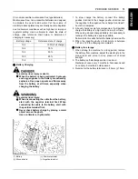
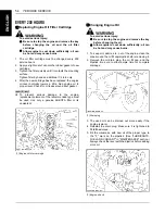
(1) Brake pedal
(2) PTO lever
(3) Key switch
(4) Throttle lever

Summary of Contents for GR1600-ID-2

Page 1: ...Europe Code No N de code K1249 7123 5 Code Nr G R 1 6 0 0 I D 2 ENGLISH FRANÇAIS DEUTSCH KUBOTA Corporation 2014 READ AND SAVE THIS MANUAL MANUEL A LIRE ET A CONSERVER DIESE ANLEITUNG SORGFÄLTIG DURCHLESEN UND AUFBEWAHREN GR1600 ID 2 MODEL MODELE MODELL PRINTED IN U S A IMPRIMÉ AUX ÉTATS UNIS IN DEN USA GEDRUCKT ...

Page 2: ...nt industriel l architecture la construction et les transports Des milliers de personnes font confiance au savoir faire de KUBOTA à sa technologie à son expérience et à son service après vente vous aussi pouvez faire confiance à KUBOTA KUBOTA ist Seit der Firmengründung im Jahre 1890 ist KUBOTA zu einem der wichtigsten Unternehmen in Japan angewachsen Hierzu hat zum großen Teil die ständige Erweit...

Page 3: ...ces which accompany them however are unified by one central commitment KUBOTA makes products which taken on a national scale are basic necessities Products which are indispensable products intended to help individuals and nations fulfill the potential inherent in their environment For KUBOTA is the Basic Necessities Giant This potential includes water supply food from the soil and from the sea ind...

Page 4: ...ENGLISH OPERATOR S MANUAL READ AND SAVE THIS MANUAL Original instructions GR1600 ID 2 MODEL 1BDAHARAP0670 ...

Page 5: ...afety and occupational medicine and all road traffic regulations must be observed at all times Any arbitrary modifications carried out to this machine may relieve the manufacturer of liability for any resulting damage or injury manufacturer or distributor of the machine the model designation of the machine the name or type of publication the part number or publication number by which the manual ma...

Page 6: ...n indication of their meaning Safety Alert Symbol Diesel Fuel Brake Parking Brake Engine Stop Preheat Engine Run Starter Control Power Take Off Clutch Control Off Position Power Take Off Clutch Control On Position Cutting Height Headlight ON Headlight OFF Fast Slow Engine Speed Control Battery Oil Pressure Coolant Temperature Mower Lowered position Mower Raised position Headlight ...

Page 7: ...t will give you long satisfactory service To obtain the best use of your riding mower please read this manual carefully It will help you become familiar with the operation of the machine and contains many helpful hints about riding mower maintenance It is KUBOTA s policy to utilize as quickly as possible every advance in our research The immediate use of new techniques in the manufacturing of prod...

Page 8: ...d Weather Starting 14 Block Heater Option 14 STOPPING THE ENGINE 14 Engine Stop Lever Inside the hood 14 WARMING UP 15 Warm up and Transmission Oil in the Low Temperature Range 15 JUMP STARTING 15 OPERATING THE MACHINE 17 OPERATING NEW MACHINE 17 Changing Lubricating Oil for New Machines 17 Engine Break in 17 Machine Break in 17 STARTING 18 Operator s Seat 18 Head Light Switch 18 Mower Lift Lever ...

Page 9: ...on Pressure 33 WHEELS 34 MAINTENANCE 35 SERVICE INTERVALS 35 PERIODIC SERVICE CHART LABEL 37 LUBRICANTS FUEL AND COOLANT 38 PERIODIC SERVICE 40 HOW TO OPEN THE HOOD 40 DAILY CHECK 40 Checking Engine Oil Level 41 Checking Amount of Fuel and Refueling 42 Checking and Cleaning Radiator and Screen to Prevent Overheating 42 Checking and Cleaning Inside of the Bonnet and Around the Mower Belt to Avoid F...

Page 10: ...YEARS 58 Flush Cooling System and Changing Coolant 58 EVERY 3000 HOURS 59 Checking Injection Pump 59 EVERY 1 YEAR 59 Replacing Air Cleaner Element 59 Checking Radiator Hose and Clamp 59 Checking Fuel Lines 59 Checking Intake Air Line 60 Checking Engine Breather Hose 60 Checking Mower Gear Box Oil Seal 60 Anti freeze 60 EVERY 4 YEARS 61 Replacing Fuel Lines 61 Replacing Engine Breather Hose 61 Repl...

Page 11: ...CONTENTS ENGLISH BATTERY TROUBLESHOOTING 69 MACHINE TROUBLESHOOTING 70 MOWER TROUBLESHOOTING 71 OPTION 72 APPENDIX 73 SOUND AND VIBRATION MEASUREMENTS 73 INDEX 74 ...

Page 12: ...e before mowing Stop machine if anyone enters the area 12 Before allowing other people to use your machine explain proper operation to them and have them read this manual before operation 13 Never allow passengers or non qualified operators on the machine at any time You must operate the machine from the seat only 14 Carefully check the area to be mowed and clear any objects such as rocks bottles ...

Page 13: ...he mower and grass catcher near public roads or highways 21 Do not operate where machine could tip or slip Do not operate near ditches holes embankments or other terrain which may collapse under the machine s weight The risk of machine tip over is increased when the ground is loose or wet 22 If the machine starts to vibrate abnormally disengage the drive to the attachments stop the engine and remo...

Page 14: ... operators should evaluate their ability to operate the machine safely enough to protect themselves and others from serious injury C Stopping 1 Make sure that the machine has come to a complete stop before dismounting 2 Before dismounting disengage the PTO lower all implements place all control levers in their neutral positions apply parking brake turn off the engine and remove the key 3 Do not pa...

Page 15: ...ad and follow all of the instructions to help protect the alternator from damage due to extreme load changes See JUMP STARTING in OPERATING THE ENGINE section Batteries contain sulfuric acid and produce explosive gases Follow the instructions below to prevent personal injury A Wear eye and skin protection A Keep sparks and flame away A Always have adequate ventilation while charging or using the b...

Page 16: ...ow to recycle or get rid of waste products A A Material Safety Data Sheet MSDS provides specific details on chemical products physical and health hazards safety procedures and emergency response techniques The seller of the chemical products used with your machine is responsible for providing the MSDS for that product upon request 1 Keep the machine and supply of fuel in locked storage and remove ...

Page 17: ...SAFE OPERATION 6 ENGLISH 8 PICTORIAL SAFETY LABELS ...

Page 18: ... 7 SAFE OPERATION ENGLISH ...

Page 19: ...SAFE OPERATION 8 ENGLISH ...

Page 20: ...r missing pictorial safety labels with new labels from your local KUBOTA Dealer 4 If a component with pictorial safety label s affixed is replaced with new part make sure new label s is are attached in the same location s as the replaced component 5 Mount new pictorial safety labels by applying on a clean dry surface and pressing any bubbles to outside edge 9 CARE OF PICTORIAL SAFETY LABELS ...

Page 21: ......

Page 22: ...rs now and record them in the space provided To be filled in by purchaser C Warranty This machine is warranted under the Kubota Limited Express warranty a copy of which may be obtained from your selling dealer No warranty shall however apply if the machine has not been handled according to the instruction given in the Operator s Manual even it is within the warranty period C Scrapping the machine ...

Page 23: ...per glow Engine stop Key stop Capacity Fuel tank L 18 Engine oil L 1 2 Radiator coolant L 2 1 Hydrostatic transmission oil L 2 8 Machine PTO Shaft drive PTO clutch Mechanical Wet Multi Discs PTO brake Wet Multi Discs Tires Front 15 x 6 00 6 Rear 20 x 10 0 8 Steering type Manual Brake Internal expanding brake Travel speed control Foot pedal Transmission Hydrostatic Traveling speeds Forward km h 0 t...

Page 24: ...over a fixed test cycle under laboratory conditions The CO measurement shall not imply or express any guarantee of the performance of a particular engine 3 Non road steady state test cycle Model RCK42 GR16 2 Mower Cutting width cm 106 7 Cutting height mm 25 to 102 Adjustment of cutting height Dial gauge Mounting method Quick joint Parallel linkage Weight kg 65 Dimensions Total length mm 750 Total ...

Page 25: ...t listed below or which are not recommended for use with the KUBOTA Machine may result in malfunctions or failures of the machine damage to other property and injury to the operator or others Any malfunctions or failures of the machine resulting from use with improper implements are not covered by the warranty Maximum axle loading weight MODEL Front axle Wf Rear axle Wr Total gross weight GR1600 I...

Page 26: ...ONTROLS 1 Easy checker TM 21 2 Head light switch 18 3 Throttle lever 19 4 KRA system override switch 27 5 Parking brake pedal 12 6 PTO lever 26 7 Hour meter 22 8 Key switch 13 9 Brake pedal 12 10 Speed control pedal 20 11 Mower lift lever 19 12 Discharge deflector ...
Page 27: ... of the machine 2 Set the front anti scalp rollers at the topmost position Turn the front wheel to the right 3 Pull the mower lift lever to raise rear links 4 Adjust the height control dial to 1 Slide the mower deck under the machine and then return wheels to straight ahead position 5 Place the mower lift lever in the LOWER position Push down the rear links to align with the mower bracket A RIGHT ...

Page 28: ...er fulcrum fixing pin and turn it counter clockwise to lock 9 Hook and raise the front link with the link fixing lever and then lay the link fixing lever onto the front bracket of the machine 10 Turn the lever fulcrum fixing pin clockwise and push it into position to fix the link fixing lever 1 L pin Unlock 2 L pin Lock 3 Rear link A UNLOCK B RELEASE 1 Front link 2 Front roller bracket 1 Link fixi...

Page 29: ...ackward and forward to make sure it is locked securely 12 Extend the universal joint cover to the coupler of the universal joint and then attach the stay to the frame with bolts A Make sure to install the stay to the frame with bolts A For dismounting the mower deck reverse the above procedures 1 Universal joint 2 Coupler A TUG 1 Universal joint cover 2 Bolt 3 Stay ...

Page 30: ...ing adjustments A Blades may be sharp When you handle blades wear heavy gloves or wrap end of blade with a rag 1 Park the machine on a level surface 2 Tire inflation pressure must be correct See TIRE AND WHEELS section 3 Raise the mower lift lever to the top position 4 Turn the cutting height control dial to adjust height to the desired height 5 Lower the mower deck by pushing the mower lift lever...

Page 31: ...mm 9 Lock the nuts 10 Measure from the outside tip of the right blade to the level surface while the blade is parallel to the rear axle This will be measurement X 11 Measure from the level surface to the bottom of the discharge cover at point D as shown in the figure below This will be measurement Y 1 Lift link 2 Cutting height fine tuning bolt 3 Lock nut A Mower cover A Bent mark line ...

Page 32: ...wer to the highest position Make sure that the stopper is in contact with the underside of the frame To adjust 1 Lift the mower to the highest position 2 Loosen the lock nut and adjust the stopper on left side so that the bolt head is in contact with the underside of the frame 3 Lower the mower deck 4 Turn the stopper counterclockwise a half turn and then secure the lock nut DISMOUNTING THE MOWER ...

Page 33: ...ngine emission control system especially with regard to deactivating or not maintaining an exhaust gas recirculation EGR system or a reagent dosing system A When a warning lamp lights up the engine is experiencing a problem which may also cause problems with the emission control system Take prompt action and rectify any incorrect operation use or maintenance of the emissions control system in acco...

Page 34: ... temperature is less than 15 remove the battery from the machine and store it somewhere warm until the next operation 4 Make sure that the PTO lever is in the DISENGAGED position 1 PTO lever ENGAGED DISENGAGED 5 Set the throttle lever 1 2 way forward 1 Throttle lever FAST SLOW 6 Insert the key into the key switch and turn clockwise 1 notch Make sure the easy checker lights are ON OFF The position ...
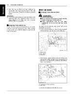
Page 35: ...ot running 4 Set the parking brake BEngine Stop Lever Inside the hood The engine stops when the key switch is turned OFF If the engine does not stop make sure the speed control pedal is in the NEUTRAL position the PTO lever is OFF the mower lowered to the ground and apply the parking brake then carefully get off the machine Then open the hood and turn engine stop lever red mark and hold it until t...

Page 36: ...ustment JUMP STARTING To avoid serious injury A Keep cigarettes sparks and flames away from battery A If machine battery is frozen do not jump start engine A Do not connect other end of negative jumper cable to negative terminal of machine battery When jump starting the engine follow the instructions below to safely start the engine 1 Bring helper vehicle with a battery of the same voltage as the ...

Page 37: ... negative ground starting system A Use only same voltage for jump starting A Use of a higher voltage source on machine could result in severe damage to machine electrical system Use only matching voltage source when Jump starting a low or dead battery condition ...

Page 38: ...f operation change the transmission fluid After the first 50 hours of operation change the oil filter cartridge See EVERY 200 HOURS in PERIODIC SERVICE section To avoid serious injury or death A Do not operate the mower without the discharge deflector in the down position To avoid serious injury A Do not allow any person other than the driver to ride on the machine A Do not drive the machine close...

Page 39: ...o ride on the machine C Travel adjustment The operator s seat position can be adjusted forward and backward by 175 mm range by pulling the seat sliding lever A After adjusting the operator s seat be sure to check that the seat is properly locked BHead Light Switch A Head lights ON B Head lights OFF 1 Adjust the operator s position 1 Seat sliding lever 2 Select Light Switch Positions 1 Head light s...

Page 40: ...n push the button at the top of the lift lever hold the button in and lower the lever down BThrottle Lever Pulling the throttle lever backward decreases the engine speed and pushing it forward increases the engine speed BParking Brake To release the parking brake depress the brake pedal again 3 Start the engine See OPERATING THE ENGINE section 4 Raise the implement 1 Mower lift lever 2 Button RAIS...

Page 41: ...more until the desired speed is reached A When the parking brake is applied the speed control pedal is locked in the NEUTRAL position STOPPING BStopping 1 Slow down the engine 2 Step on the brake pedal 3 After the machine has stopped disengage the PTO lower the implement to the ground and set the parking brake CHECK DURING DRIVING BImmediately Stop the Engine if A The engine suddenly slows down or...

Page 42: ...eating Indicator When the key switch is in the PREHEAT position the glow plug indicator illuminates A For checking and servicing of your machine consult your local KUBOTA Dealer for instructions BEngine Overheating Precautions If the coolant temperature warning light come on or the buzzer sounds take the following actions 1 Stop machine operation in a safe place disengage the mower deck and keep t...

Page 43: ... Shut off the engine A Remove the key 1 When parking be sure to set the parking brake To apply the parking brake Depress the brake pedal firmly with your right foot and the parking brake pedal simultaneously with your left foot Then release the brake pedal while holding the parking brake pedal down 2 Before getting off the machine disengage the PTO lower all implements to the ground place all cont...

Page 44: ...use a suitable tie down for the hood A Apply the parking brake and lift down the mower deck to the lowest position A Remove the key A Secure the portions of the machine which are shown in the figure below by using heavy duty straps FRONT REAR 2 Do not attempt to tow this machine or damage to the transmission may result 3 Follow all federal and local regulations for securement 1 Heavy duty strap 1 ...

Page 45: ...tting height for the first mowing then reset to the desired height and mow again Allow the grass to grow to 80 mm then cut off only the top inch 5 For best appearance grass should be cut in the afternoon or evening when it is free of moisture To avoid serious injury A Clear the work area of objects which might be picked up and thrown by blades A Keep bystanders and animals away from the mowing are...

Page 46: ...e button This lowers the mower deck from the Transport position to the Operating position 6 Use the higher settings for mowing in a rough area or when mowing tall grass Lower settings should be used only for smooth lawns where short grass is desired RCK42 1 Mower lift lever 2 Cutting height control dial 1 Anti scalp roller Front 2 Anti scalp roller Rear ...

Page 47: ...art the engine 2 Set the throttle lever to the FAST position 3 Push down the PTO lever to the ENGAGED position BPTO Lever To engage mower blade push the PTO lever to the ENGAGED position To stop the mower blades pull the PTO lever to the DISENGAGED position A When attempting to operate the machine in reverse with the PTO engaged the engine will shut down A If you dismount from the seat while the P...

Page 48: ...nders especially children have entered the area 7 Depress the speed control pedal with the heel of your right foot to move in the reverse direction To avoid serious injury or death A Engine components can get extremely hot from operation To prevent severe burns do not touch these areas while the engine is running or immediately after it is turned off Never operate the engine with heat shields or g...

Page 49: ...id serious injury A Shut off the engine and remove the key 1 Park the machine on the firm and level surface 2 Loosen the bolt with a hexagonal hole M6 3 Unlatch the clamp holding the mulching cover 4 Unhook the mulching cover in the back 1 Slide the mulching cover a little backward 2 Lift the mulching cover slightly and unhook it 5 Lift the discharge deflector and the mower cover 1 Mulching cover ...

Page 50: ...mp of the mulching cover and tighten the bolt with a hexagonal hole M6 to 9 81 to 11 3 N m 1 0 to 1 15 kgf m Make sure the cover is fixed to the mower deck securely with no gap for discharge To avoid serious injury A Do not operate the mower with the mulching cover not certainly hooked 1 Discharge deflector 2 Mower cover 3 Mulching cover 1 Discharge deflector 2 Mower cover 3 Mulching cover 4 Stay ...

Page 51: ...ack the discharge deflector and the mower cover to the original position 6 Fasten the clamp of the mulching cover and make sure it is fixed to the mower deck securely To avoid serious injury A Do not operate the mower with the mulching cover not certainly hooked ADJUSTING THE CLAMP To avoid serious injury A Shut off the engine and remove the key Make sure the mulching cover is fixed securely If no...

Page 52: ...most fasten the clamp and tighten the bolt with a hexagonal hole M6 to 9 81 to 11 3 N m 1 0 to 1 15 kgf m 4 Adjust the hook plate so that the clamp would not be loosen and then fasten the bolts securely A Do not touch the clamp stay for adjusting the clamp in the mulching position 1 Discharge deflector 2 Mower cover 3 Mulching cover 1 Clamp 2 Hook plate 3 Bolt 4 Bolt with a hexagonal hole M6 ...

Page 53: ... Do not direct jet towards hydraulic elements CLEANING THE MOWING SYSTEM After each use carefully clean the mowing deck particularly underneath Switch the engine off before cleaning your machine Operate the mowing system for a few minutes after cleaning A If the mower was used under very difficult conditions very wet grass mowing in a very low position it may be necessary to remove the cutting dec...

Page 54: ...essed air To avoid serious injury A Never operate machine with a loose rim wheel or axle A Whenever bolts are loosened retighten to specified torque A Check all bolts frequently and keep them tightened BInflation Pressure Though the inflation pressure is factory set to the prescribed level it naturally drops slowly in the course of time Thus check it everyday and inflate as necessary Turf tire Tir...

Page 55: ...uts tighten the wheel nut to the following torques then recheck after travelling 200 m changing directions several times 1 Front tire assy 2 Axle 3 Plain washer 4 Cotter pin 5 Front wheel cap 6 Plain washer Thin type 1 Plain washer 2 Plain washer 3 Key 4 Rear axle 5 Rear tire 6 Plain washer 7 Retaining ring 8 Rear wheel cap 1 Bolt 2 Adapter 3 Wheel 4 Nut Outside 108 to 125 N m 11 1 to 12 7 kgf m A...

Page 56: ... Hr 46 6 PTO control system Check every 50 Hr 46 7 Oiling every 50 Hr 48 8 Greasing every 50 Hr 48 9 Mower gear box oil Check every 50 Hr 47 Change every 150 Hr 53 10 Air cleaner element Clean every 50 Hr 47 1 Replace every 1 year 59 11 Battery condition Check every 50 Hr 50 12 Brake Check every 100 Hr 52 13 Fan drive belt Check every 100 Hr 52 2 14 Fuel filter element Check every 100 Hr 52 Replac...

Page 57: ...hardening scar or deformation or damage occurred 20 Radiator Clean every 2000 Hr or 2 years 58 4 21 Coolant Change every 2000 Hr or 2 years 58 4 22 Fuel line Check every 1 year 59 R Replace every 4 years 61 2 23 Radiator hose and clamp Check every 1 year 59 R Replace every 4 years 61 2 24 Intake air line Check every 1 year 60 R Replace every 4 years 61 25 Mower gear box oil seal Check every 1 year...

Page 58: ... CHART LABEL This label is for your quick reference The label shows the recommended services from daily to every 4 years including fluid capacities tire pressure and so on For detail refer to operator s manual 1 Periodic service chart label ...

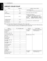
Page 59: ...ee following Engine Oil Above 25 SAE30 SAE10W 30 or 15W 40 0 to 25 SAE20 SAE10W 30 or 15W 40 Below 0 SAE10W SAE10W 30 or 15W 40 Transmission case 2 8 L KUBOTA UDT or SUPER UDT fluid 2 Front axle case Mower gear box 0 35 L Greasing No of greasing points Capacity Type of grease Engine transmission universal joint 1 Until grease overflows Multipurpose EP2 Grease NLGI Grade No 2 King Pin 2 Front axle ...

Page 60: ...istribution a cetane number greater than 45 and a fatty acid methyl ester FAME content lower than 7 volume per volume v v shall be used C Transmission Oil The oil used to lubricate the transmission is also used as hydraulic fluid To insure proper operation of the hydraulic system and to complete lubrication of the transmission it is important that a multi grade transmission fluid is used in this s...

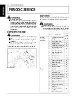
Page 61: ...tant to know the condition of the machine Check it before starting To avoid serious injury A Be sure to check and service the machine on a level surface with the engine shut off the key removed and the parking brake securely set No Check item Ref Page Walking around the machine 1 Tire pressure wear and damage 33 43 2 Oil and water leak 3 Engine oil level 41 4 Transmission fluid level 44 5 Coolant ...

Page 62: ...the old oil and oil filter Never mix 2 different types of oil A Use the proper Engine Oil SAE according to the ambient temperatures See LUBRICANTS FUEL AND COOLANT in MAINTENANCE section While sitting in the operator s seat 1 Speed control pedal Brake pedal 52 2 Brake lock 3 Other movable parts 45 Turning the key switch on 1 Performance of the easy checker light 21 Starting the engine 1 Color of t...

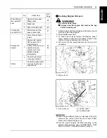
Page 63: ...gine start A Be careful not to spill fuel during refueling If a spill should occur wipe it off at once or it may cause a fire A To prevent condensation water accumulation in the fuel tank fill the tank before parking overnight BChecking and Cleaning Radiator and Screen to Prevent Overheating To avoid serious injury or death A Engine components can get extremely hot from operation To prevent severe...

Page 64: ...d clean inside of the bonnet and around the mower belt Especially dry grass and leaves around the exhaust manifold the muffler or around the mower belt may ignite After using air blowing and pressure washing make sure there is nothing flammable around the exhaust manifold the muffler or around the mower belt Grass twigs dirt or chaff in the bonnet may cause fire BChecking Tire Pressure To avoid se...

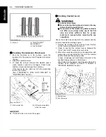
Page 65: ...n cool slowly rotate cap to the first stop and allow sufficient time for excess pressure to escape before removing the cap completely Check the coolant level daily both the radiator and the recovery tank before starting engine 1 Remove the radiator cap and check to see that the coolant level is just below the fill port 2 Check to see that the coolant level is between the FULL and LOW marks of reco...

Page 66: ...relevant spot Otherwise the machine may get damaged EVERY 50 HOURS BChecking Engine Start System The Engine Start System in your machine is designed to protect you while operating Check the Engine Start System periodically It is recommended to check the Engine Start System before daily operation To avoid serious injury A Do not allow anyone near the machine while testing A If the machine does not ...

Page 67: ...he brake pedal 4 Stand up DO NOT GET OFF THE MACHINE 5 Engine should shut off BChecking PTO Control System The PTO control system in your machine is designed to protect you while operating Check the PTO control system periodically It is recommended to check the PTO control system before daily operation To avoid serious injury A Do not allow anyone near the machine while testing A If the machine do...

Page 68: ...he case 3 Replace the air cleaner element if Once yearly or after every sixth cleaning whichever comes first A Checked to see if the evacuator valve is blocked with dust A Operating in dusty conditions requires more frequent maintenance A The air cleaner uses a dry element never apply oil A Do not run the engine with the filter element removed A Align the arrow marks when reinstalling the cover If...

Page 69: ...ure to stop the engine and remove the key before greasing Grease the following locations BOiling To avoid serious injury A Be sure to stop the engine and remove the key before oiling Oil the following locations 1 Check plug Oil filler plug 1 Engine transmission universal joint Apply grease on the spline shaft 2 Engine transmission universal joint Nipple 1 King pin LH RH 1 Speed control pedal shaft...

Page 70: ...d control pedal shaft LH 1 PTO lever fulcrum 1 Mower lift lever fulcrum 1 Seat adjuster 1 Around the hole of the mower link LH RH 2 Around the pin of the mower link LH RH 3 Pivot of mower link LH RH 4 Pivot of liftarm LH RH 1 Front link ...

Page 71: ...nia to cause cancer and birth defects or other reproductive harm WASH HANDS AFTER HANDLING A Never remove the battery cap while the engine is running A Keep electrolyte away from eyes hands and clothes If you are spattered with it wash it away completely with water immediately and get medical attention A Keep open sparks and flames away from the battery at all times Hydrogen gas mixed with oxygen ...

Page 72: ...bject across the posts Use a voltmeter or hydrometer 1 To slow charge the battery connect the battery positive terminal to the charger positive terminal and the negative to the negative then charge for at least 1 hour at 4 5 amperes 2 A boost charge is only for emergencies It will partially charge the battery at a high rate and in a short time When using a boost charged battery it is necessary to ...

Page 73: ... fuel filter if it is clogged by debris or contaminated with water consult your local KUBOTA Dealer to replace it BChecking Brake To avoid serious injury A When checking brake park the machine on a flat area block wheels stop the engine and remove the key Correct free travel ranges from 15 to 25 mm If it is not correct consult your local KUBOTA dealer to adjust BChecking Fan Drive Belt Tension To ...

Page 74: ...ng the oil A Remove the belt cover as shown in figure below by loosening the bolts as shown in figure below 1 To drain the used oil remove the filler plug and the drain plug at the gear box tilt the mower deck and drain the oil completely into the oil pan 2 Fill with the new oil See LUBRICANTS FUEL AND COOLANT in MAINTENANCE section 3 After filling reinstall the filler plug 1 Right cover 1 Fan dri...

Page 75: ...e engine replacement element of the recommended type must be used Use only a genuine KUBOTA filter or its equivalent BChanging Engine Oil To avoid serious injury A Be sure to stop the engine and remove the key before changing the oil A Allow engine to cool down sufficiently oil can be hot and may cause burns 1 To keep dirt debris etc out of the engine clean the area around the oil fill cap dipstic...

Page 76: ...y A Be sure to stop the engine and remove the key before changing the oil filter cartridge A Allow transmission case to cool down sufficiently oil can be hot and may cause burns 1 The oil filter cartridge must be changed every 200 service hours 2 Remove rear cover 3 Remove the oil filter cartridge by using the filter wrench 4 Lightly tighten the screw A by using a screwdriver 5 Apply a slight coat...

Page 77: ...travel of front axle EVERY 400 HOURS BChanging Transmission Fluid To avoid serious injury A Be sure to stop the engine and remove the key before changing or checking the oil A Allow transmission case to cool down sufficiently oil can be hot and may cause burns The fluid in the transmission case is also used for the hydrostatic drive system 1 To drain the transmission oil place oil pan underneath t...

Page 78: ... Transmission Strainer When changing the transmission fluid disassemble and rinse the strainer with nonflammable solvent to completely clean off filings Check O rings Replace it if damaged cracked or hardened When reassembling be careful not to damage the parts A Since the fine filings in the oil can damage the precision component parts of the hydraulic system the end of the suction line is provid...

Page 79: ...ll coolant is drained install the drain plugs 4 Fill with clean water and cooling system cleaner 5 Follow directions of the cleaner instruction 6 After flushing fill with clean water and anti freeze until the coolant level is just below the fill port on the radiator Install the radiator cap securely 7 Fill with coolant up to FULL on the recovery tank 8 Start and operate the engine for a few minute...

Page 80: ...the engine and remove the key when attempting to make the following checks and changes A Never fail to check the fuel lines periodically The fuel lines are subject to wear and aging Fuel may leak out onto the running engine causing a fire The fuel line is made of rubber and ages regardless of service period 1 Check the fuel line connections If the fuel line and clamps are found to be damaged or de...

Page 81: ...nditions Keep fire and children away from anti freeze A When draining fluids from the engine place some container underneath the engine body A Do not pour waste onto the ground down a drain or into any water source A Also observe the relevant environmental protection regulations when disposing of anti freeze Always use a 50 50 mix of long life coolant and clean soft water in KUBOTA engines Consult...

Page 82: ...ta represent industry standards that necessitate a minimum glycol content in the concentrated anti freeze EVERY 4 YEARS BReplacing Fuel Lines Consult your local KUBOTA Dealer for this service BReplacing Engine Breather Hose Consult your local KUBOTA Dealer for this service BReplacing Radiator Hose Replace hoses and clamp bands every 4 years or earlier if you checked and found that hoses are swolle...

Page 83: ...urn 1 4 turn to remove bulb from the socket 4 Install new bulb to the socket 5 Install the socket in housing 6 Close hood B Replacement of the Indicator light bulb 1 Open hood 2 Turn bad bulb socket to the left And remove it 3 Pull bulb from the socket 4 Push new bulb into the socket 5 Install the socket 6 Close hood 2 Slow blow fuse A Starter 3 KRA system A Left rear tire FUSE NO ID LABEL CAPACIT...

Page 84: ...des 1 Remove the mower deck from the machine and turn it over to expose the blades 2 Wedge a block of wood between the blade and mower housing as illustrated 3 The bolt for black blade has right hand threads turn counterclockwise to loosen The bolt for red blade has left hand threads turn clockwise to loosen 4 To sharpen the blades yourself clamp the blade securely in a vise Use a large mill file ...

Page 85: ...DISMOUNTING THE MOWER DECK 2 Loosen the bolts as shown in the figure below and remove cover A B C and D as shown in figure below 3 Clean around the pulleys to remove the belt from the pulleys Slip the belt over the top of the pulley 4 Remove the right bracket which mount the gear box to the mower deck 1 Spindle holder 2 Blade 3 2 Cup washers 4 Plain washer 5 Bolt 6 Spindle guard 1 Cover A 2 Cover ...

Page 86: ...he above procedure BBleeding Fuel System Air must be removed 1 When the fuel filter or lines are removed 2 When tank is completely empty 3 After the machine has not been used for a long period of time C Bleeding procedure is as follows 1 Fill the fuel tank with fuel 2 Turn the key switch to the ON position and hold it for about 10 seconds 3 Start the engine and run for about 30 seconds and then st...

Page 87: ...m kgf m 23 6 27 4 2 4 2 8 29 4 34 3 3 0 3 5 3 8 N m kgf m 47 5 57 0 4 84 5 82 61 0 73 2 6 22 7 47 M10 N m kgf m 48 1 55 8 4 9 5 7 60 8 70 5 6 2 7 2 7 16 N m kgf m 75 9 89 5 7 74 9 12 101 7 122 10 37 12 44 M12 N m kgf m 77 5 90 1 7 9 9 2 103 117 10 5 12 0 1 2 N m kgf m 108 5 130 2 11 07 13 29 149 2 179 0 15 22 18 27 M14 N m kgf m 124 147 12 6 15 0 167 196 17 0 20 0 9 16 N m kgf m 149 2 179 0 15 22 ...

Page 88: ... Hexa Bolt Head size B mm No mark 7T N m kgf m N m kgf m M8 12 or 13 17 8 20 6 19 2 0 6 1 9 2 1 2 0 0 1 23 5 27 5 25 5 2 0 2 4 2 8 2 6 0 2 M10 14 or 17 39 3 45 1 42 2 2 9 4 0 4 6 4 3 0 3 48 1 55 9 52 0 3 9 4 9 5 7 5 3 0 4 M12 17 or 19 62 8 72 6 67 7 4 9 6 4 7 4 6 9 0 5 77 6 90 2 83 9 6 3 8 0 9 2 8 6 0 6 M14 19 or 22 107 9 125 5 116 7 8 8 11 0 12 8 11 9 0 9 123 6 147 0 135 3 11 7 12 6 15 0 13 8 1 2...

Page 89: ... Drain fuel tank fuel lines 8 Store the machine where it is dry and sheltered from rain Cover the machine with a tarpaulin 9 Moisture content in most grasses can damage the mower if these components are not properly cleaned after use Make sure the mower is clean before storage 10 Jack the machine up and place blocks under the front and rear axles so that all 4 tires are off the ground Keep the tir...

Page 90: ... Fuel quality is poor Black smoke is emitted from the muffler during operation power output is lowered A Air cleaner element clogged Bluish white smoke is emitted from the muffler during operation A Too much engine oil Engine will not idle A Fuel filter is clogged Engine overheats A Low coolant level A Loose or defective fan belt A Coolant flow route corroded If Probable cause Starter does not fun...

Page 91: ...robable cause Machine operation is not smooth A Hydrostatic transmission oil is low Machine does not move while engine is running A Parking brake is on A Transmission oil is insufficient Machine moves when speed control pedal is not depressed Engine is operated A Hydrostatic neutral system is not correctly adjusted ...

Page 92: ...ire inflation A Mower rollers not adjusted correctly Blades scalping grass A Cutting height too low A Blades speed too fast A Ridges in terrain A Rough or uneven terrain A Bent blade s A Low tire inflation A Anti scalp rollers not adjusted correctly Belt slipping A Belt tension incorrect A Mower deck plugged A Debris in pulleys A Worn belt Excessive vibration A Debris on mower deck or in pulleys A...

Page 93: ...72 OPTION ENGLISH OPTION Consult your KUBOTA Dealer for further details ...

Page 94: ...on Level Measured Per ISO5395 A The published measurements were obtained according to the standard test procedure in EN ISO 5395 1 2013 A1 2018 The level when in use is dependent on the operating environment driving style and condition of the machine Take steps to reduce vibration eg correct tire pressure reducing speed over rough ground Model Engine speed Sound pressure at the operator s position...

Page 95: ...18 Hourmeter 22 Immediately Stop the Engine if 20 Inflation Pressure 33 Injection Pump 59 Inside of the Bonnet and Around the Mower Belt to Avoid Fire Hazard 43 Intake Air Line 60 Intake Air Line 61 Key Switch 13 KRA system Normal Operating Mode 26 KRA system Override Mode 27 Lubricating All Grease Fittings 45 Lubricating Oil for New Machines 17 Machine Break in 17 Mounting the Mower Deck 6 Movabl...

Page 96: ...struction de machines selon la directive CE 2006 42 CE et la directive 2000 14 CE modifiée par 2005 88 CE ANNEXE VI et satisfait également la compatibilité électromagnétique de la directive CE 2014 30 UE et à la limitation de l utilisation de certaines substances dangereuses conformément à la directive RoHS 2011 65 UE Entwurf und Konstruktion dieser Maschine entsprechen den erforderlichen grundleg...

Reviews: